Display device

A technology for display devices and display panels, which can be used in identification devices, nonlinear optics, instruments, etc., to solve problems such as inability to view images and depending on viewing angles.

Inactive Publication Date: 2009-09-02
SEIKO INSTR INC
View PDF6 Cites 63 Cited by
  • Summary
  • Abstract
  • Description
  • Claims
  • Application Information

AI Technical Summary

Problems solved by technology

For example, when viewing a display by using sunglasses, there are cases where images displayed on the display device cannot be viewed depending on the viewing angle
This is because the image light passing through the liquid crystal panel 50 has polarization properties, and when the polarization direction of the image light and the polarization direction of the sunglasses are perpendicular to each other, the image cannot be viewed.

Method used


Image

  • Display device
  • Display device
  • Display device

Examples


no. 1 example

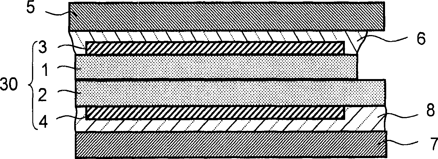
figure 1 is a schematic longitudinal sectional view showing the display device according to the first embodiment of the present invention. figure 1 It is shown that a glass substrate 1 including a transparent substrate on the display surface side, a glass substrate 2 as a transparent substrate on the rear surface side, a liquid crystal layer (not shown) sandwiched between the glass substrate 1 and the glass substrate 2 are shown. shown), a polarizing plate 3 serving as an optical film attached to the display surface side of the glass substrate 1, and a polarizing plate 4 serving as an optical film attached to the rear surface of the glass substrate 2. Panel 30. On the display surface side of the liquid crystal panel 30 , tempered glass 5 serving as a first glass plate is bonded with an optical adhesive 6 serving as a first adhesive having light-transmitting properties. Also on the rear surface side of the liquid crystal panel 30, tempered glass 7 serving as a second glass p...

no. 2 example

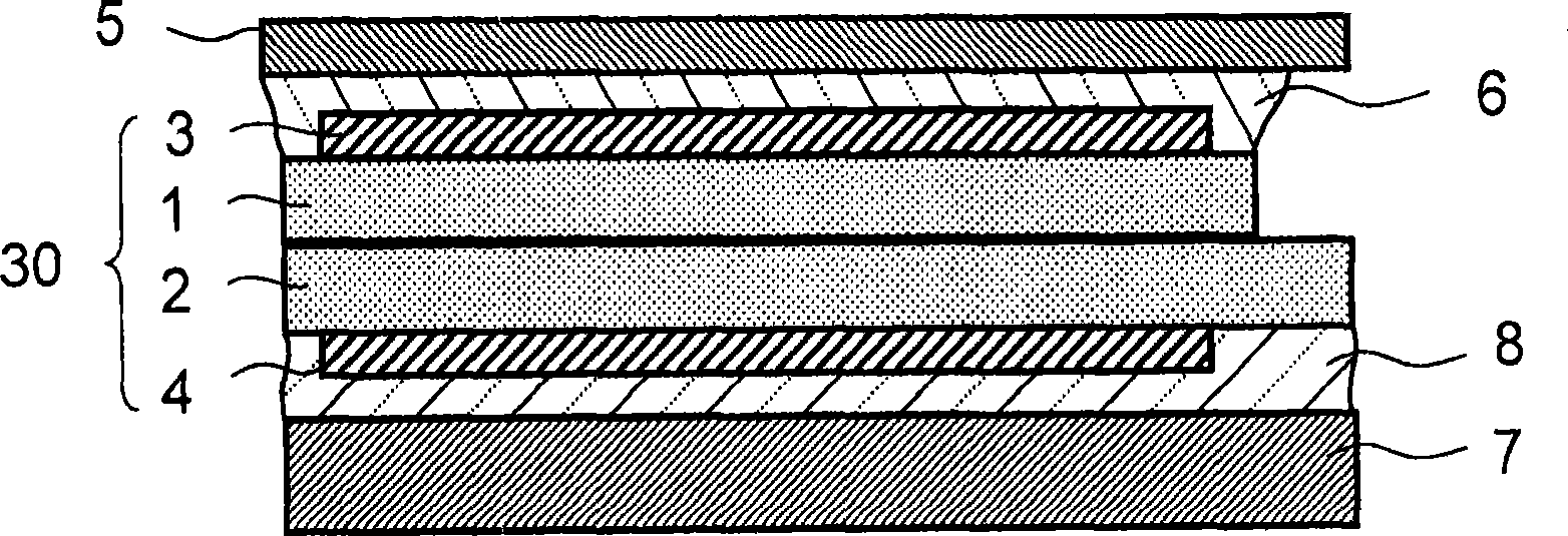
figure 2 is a schematic longitudinal sectional view showing a display device according to a second embodiment of the present invention. The second embodiment and figure 1 The first embodiment differs in the tempered glass 5 used as the first glass plate, the tempered glass 7 used as the second glass plate, and the thickness of the liquid crystal panel 30 . other structures with figure 1 The first embodiment is similar to the first embodiment, so the different parts will be mainly described below. The same parts or parts having the same function are denoted by the same reference numerals.

[0031] Such as figure 2 As shown, a liquid crystal panel 30 is formed of two glass substrates 1 and 2 , a liquid crystal layer (not shown), and polarizing plates 3 and 4 . The display surface side of the liquid crystal panel 30 and the tempered glass 5 are bonded and fixed to each other by the optical adhesive 6 serving as the first adhesive, and the rear surface side of the liquid c...

no. 3 example

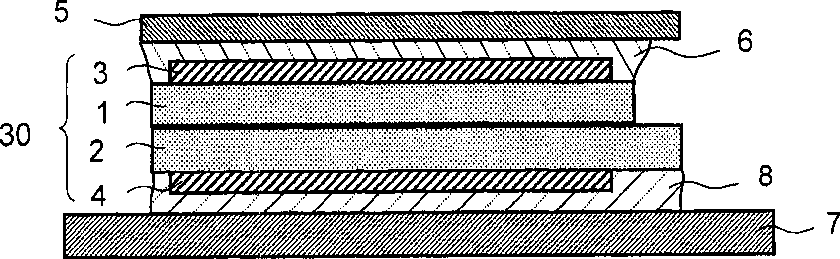
image 3 is a schematic longitudinal sectional view showing a display device according to a third embodiment of the present invention. The third embodiment and figure 2 The second embodiment differs in the thickness of the glass substrate 1 forming the liquid crystal panel 30 and the external shape of the tempered glass 7 . Therefore, the difference between them will be mainly described below. The same parts or parts having the same function are denoted by the same reference numerals.

[0036] Such as image 3As shown, a liquid crystal panel 30 is formed of two glass substrates 1 and 2 , a liquid crystal layer (not shown), and polarizing plates 3 and 4 . The display surface side of the liquid crystal panel 30 and the tempered glass 5 serving as the first glass plate are bonded and fixed to each other by the optical adhesive 6 serving as the first adhesive, and the rear surface side of the liquid crystal panel 30 and the second glass plate are bonded and fixed. The tempere...


PUM

PropertyMeasurementUnit
thicknessaaaaaaaaaa
thicknessaaaaaaaaaa
thicknessaaaaaaaaaa

Abstract

An enforcing glass plate is attached to the entire display region of the display side and the opposite side of a liquid crystal panel (30) so as to improve the applied weight resistance against an external shock or pressure, which enables reduction of the thickness of the liquid crystal panel (30). That is, a display device includes: a liquid crystal panel (30) which sandwich liquid crystal inside two transparent substrates and having an optical film arranged on at least one of the external surfaces of the transparent substrates; a first glass plate bonded to the display surface side of the liquid crystal panel (30) via a first adhesive formed by an optical adhesive or a transparent adhesive sheet; and a second glass bonded to the rear surface side of the liquid crystal panel (30) via a second adhesive formed by an optical adhesive or a transparent adhesive sheet.

Description

technical field [0001] The present invention relates to a display device in which a flat display unit such as a liquid crystal panel is used. Specifically, the present invention relates to a structure of a display device in which a cover plate or a touch screen is arranged to a display surface side of a flat display unit. Background technique [0002] Flat display devices are widely put into practical use as display portions of cellular phones, personal digital assistants (PDAs), electronic dictionaries, car navigation systems, music players, and the like. In particular, a display device using a liquid crystal panel is light and thin, and is used as a display section of a personal computer or a display section of a portable device due to its low power consumption characteristics. [0003] Figure 15 A cross-sectional structure of a display device using a liquid crystal panel with touch switches is shown. The display device includes: a liquid crystal panel 50 including a li...

Claims


Application Information

Patent Timeline
Patent Type & Authority Applications(China)
IPC IPC(8): G02F1/1333G02F1/13357G09F9/00
CPCG02F2201/503G02F1/133308G02F2202/28G02F1/1333G02F1/1335G09F9/00
Inventor 松平努海老原照夫原光义
Owner SEIKO INSTR INC
Why Eureka
Try Eureka