battery module unit

A technology for battery modules and battery cells, applied in electrical components, battery pack components, circuits, etc., can solve problems such as reduced operability, battery module deviation, and overall length of battery module units, and achieve the effect of improving operability

Active Publication Date: 2015-10-21
HONDA MOTOR CO LTD
View PDF3 Cites 0 Cited by
  • Summary
  • Abstract
  • Description
  • Claims
  • Application Information

AI Technical Summary

Problems solved by technology

[0007] However, since the battery module is constituted by stacking a plurality of battery cells, there is a problem that the tolerance of the thickness of each battery cell accumulates to cause variation in the length of the battery module. tolerance absorbing mechanism
However, when the longitudinal end faces of the two battery modules are opposed to each other and are integrated, if a tolerance absorbing mechanism is provided at both ends, the overall length of the battery module unit becomes larger, which may cause Reduced operability

Method used


Image

  • battery module unit
  • battery module unit
  • battery module unit

Examples


Embodiment Construction

[0038] Below, based on Figure 1 to Figure 6 , the embodiment of the present invention will be described.

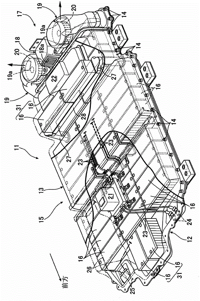
[0039] Such as figure 1 As shown, the battery pack 11 of an electric vehicle has a battery case 15 obtained by bonding a synthetic resin battery cover 13 to the upper surface of a metal battery tray 12 and fastening it with bolts 14 . . . A plurality of battery modules 16 . . . are mounted on the surface.

[0040] A cooling device 17 provided at the rear of the battery pack 11 includes a suction duct 18 disposed in the center in the vehicle width direction, and a pair of left and right discharge ducts 19 disposed on both sides of the suction duct 18 in the vehicle width direction. A cooling air inlet 18 a for sucking air outside the battery pack 11 into the inlet duct 18 is opened toward the front on the upper front surface of the inlet duct 18 . In addition, electric cooling fans 20 and 20 are respectively accommodated inside the discharge ducts 19 and 19, and the co...


PUM


Abstract

The invention provides a battery module unit, which is formed by integratedly serially connecting a pair of battery modules together, and can be used to reduce the increasing of the total length caused by the tolerance absorption mechanism used for absorption of the length difference of the battery modules. A first end plate (37) is clamped between the pair of battery modules (16) is formed by a shared member, therefore the rigidity of the battery module unit (31) can be improved, and the anti-vibration performance can be improved. In addition, because the tolerance absorption mechanism is disposed between the two battery modules, the tolerance absorption mechanism is protruded from two ends of the battery module units, and the miniaturization of the battery module units can be realized.

Description

technical field [0001] The present invention relates to a battery module unit constituted by arranging a pair of battery modules in series and integrating them, the battery module being sandwiched between a first end plate and a second end plate by stacking a plurality of battery cells The first end plate and the second end plate are connected by a connecting member. Background technique [0002] According to the following Patent Document 1, there is known a structure in which a pair of end plates are brought into contact with both end portions of a plurality of stacked battery cells, and the pair of end plates are fastened to the restraining band (connecting member) by bolts. ) to form a battery module in which a plurality of battery cells are integrated in a laminated state. [0003] 【Prior technical literature】 [0004] 【Patent Literature】 [0005] [Patent Document 1] Japanese Patent Laid-Open No. 2009-48973 [0006] If the battery module unit is constituted by integr...

Claims


Application Information

Patent Timeline
Patent Type & Authority Patents(China)
IPC IPC(8): H01M2/10
CPCY02E60/10
Inventor 木村有寿高桥正树
Owner HONDA MOTOR CO LTD
Why Eureka
Try Eureka