

Production method of multi-gauge strips
A simultaneous manufacturing and stripping technology, applied in the direction of electrical components, electrical solid devices, circuits, etc., can solve the problems of unused, poor competitiveness, etc.
- Summary
- Abstract
- Description
- Claims
- Application Information
AI Technical Summary
Problems solved by technology
Method used
Image

Examples
example 1
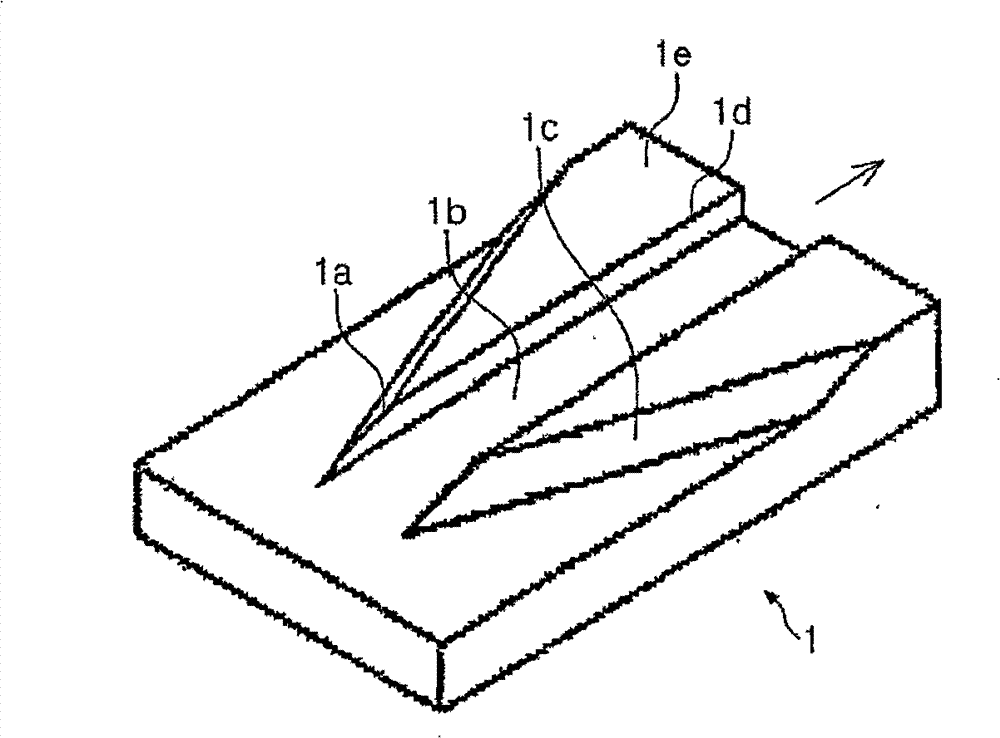
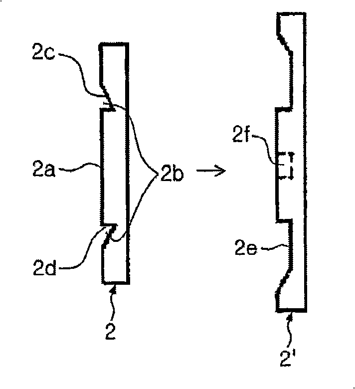
[0047] A first embodiment of the method of manufacturing multi-thickness strips according to the invention comprises the steps of: forming the strip-shaped material (10) into a processed strip (20), in which A thick portion (21) is formed at the center portion in the direction, and a groove (concave) (22) is formed at each end of the lower side; and the processed strip (20) is formed into a multi-thickness strip (30) , the multi-thickness strip (30) is formed with a thin portion (32) on each side of the thick portion (31) at the center, as Figure 7 and Figure 8 shown in .
[0048] Here, the shape of the groove ( 22 ) is not particularly limited, and may include a curved groove, such as a circular or elliptical type or a trapezoid.
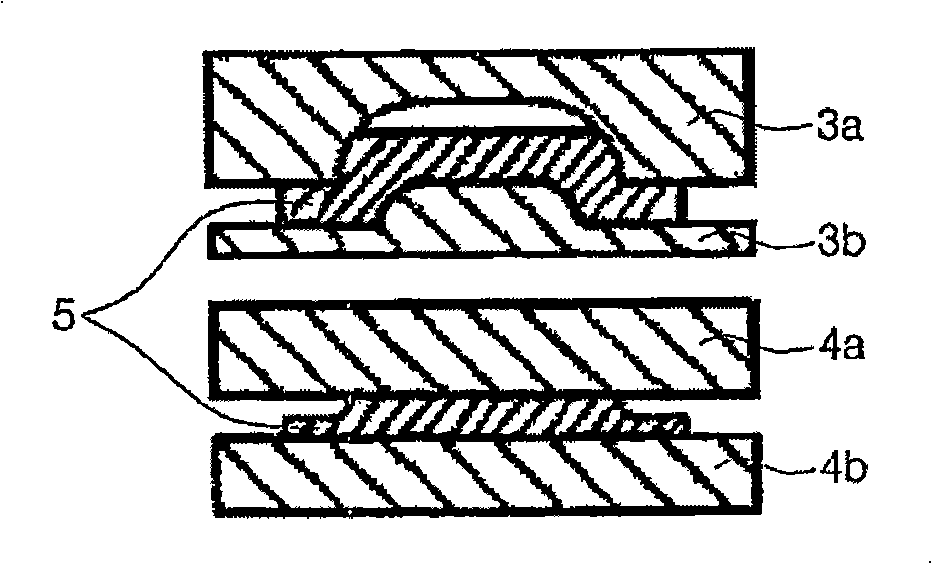
[0049] The processed strip (20) is formed by a first lower roller (101) having at least one protrusion (101) at each side end in the width direction and a first upper roller having a flat surface (not shown) and the multi-thickness band (30) i...
example 2
[0056] In the method described in this second example of the invention, when forming the processed strip (20) into a multi-thickness strip (30) in the above example one, the upper side at the center of the thick portion (31) is formed There is a square recessed area (33), resulting in Figure 9 The W-shaped multi-thickness strip (30) shown in.
[0057] In this method, an upper punch having a groove (241) forming a square protrusion (242) at the center of the lower side may be used as an upper punch (240) for forming a W-shaped multi-thickness band (30). In this method, the pressure inside the groove (241) increases as the volume of the square protrusion (242) increases compared to the case where only the groove (241) is formed in the upper punch (240), however, forming The space on the underside of the processed strip (20) increases the flexibility of the material. Therefore, high pressure is not required, and forming can be performed without restriction on ejection and tran...
example 3
[0059] Example three of the invention depicts a method comprising the steps of forming the strip material into a processed strip (40), wherein the processed strip (40) has a plurality of grooves (42) on its underside, and having thick portions (41) between the grooves; and by forming the grooves in the inner portion of the processed strip (40) as thin portions and then simultaneously forming the grooves at each end as thin Section, the step of forming the processed strip (40) into a multi-thickness strip (50) comprising a plurality of thick sections (51) and thin sections (52) between the thick sections, as Figure 10 shown in .
[0060] In this method, when forming the processed strip (40) into a multi-thickness strip (50), preferably, the groove at the center of the processed strip (40) and the peripheral groove are sequentially Shaping takes place, and finally grooves at the edges of the processed strip (40) are formed as thin sections. In this case, the groove may be for...
PUM
 Abstract
Description
Claims
Application Information