Supercharge Your Innovation With Domain-Expert AI Agents!

Zero-clearance bolted joint

A technology of bolted joints, bolts, applied in the direction of screws, connecting members, shrinkage connections, etc.

Active Publication Date: 2014-11-26
ACUMENT INTPROP LLC
View PDF4 Cites 0 Cited by
  • Summary
  • Abstract
  • Description
  • Claims
  • Application Information

AI Technical Summary

Problems solved by technology

However, normally the bolted joints prevent the gears from moving relative to the case
This is because the bolts are not able to generate enough tension to stop the gears from slipping which would cause the bolts to back off and disengage

Method used


Image

  • Zero-clearance bolted joint
  • Zero-clearance bolted joint
  • Zero-clearance bolted joint

Examples


Embodiment Construction

[0024] While the invention is susceptible of embodiments in different forms, with respect to the embodiments of the invention shown in the drawings and described in detail herein, it should be understood that the description herein is to be considered as illustrative of the principles of the invention and that It is not intended to limit the invention to the embodiments shown and described herein.

[0025] The present invention relates to a zero-backlash bolting joint that can be used, for example, as a method of fastening a differential case to a ring gear that is not critical of alignment and minimizes multiple passes under load on the ring gear. Gear slippage while cycling.

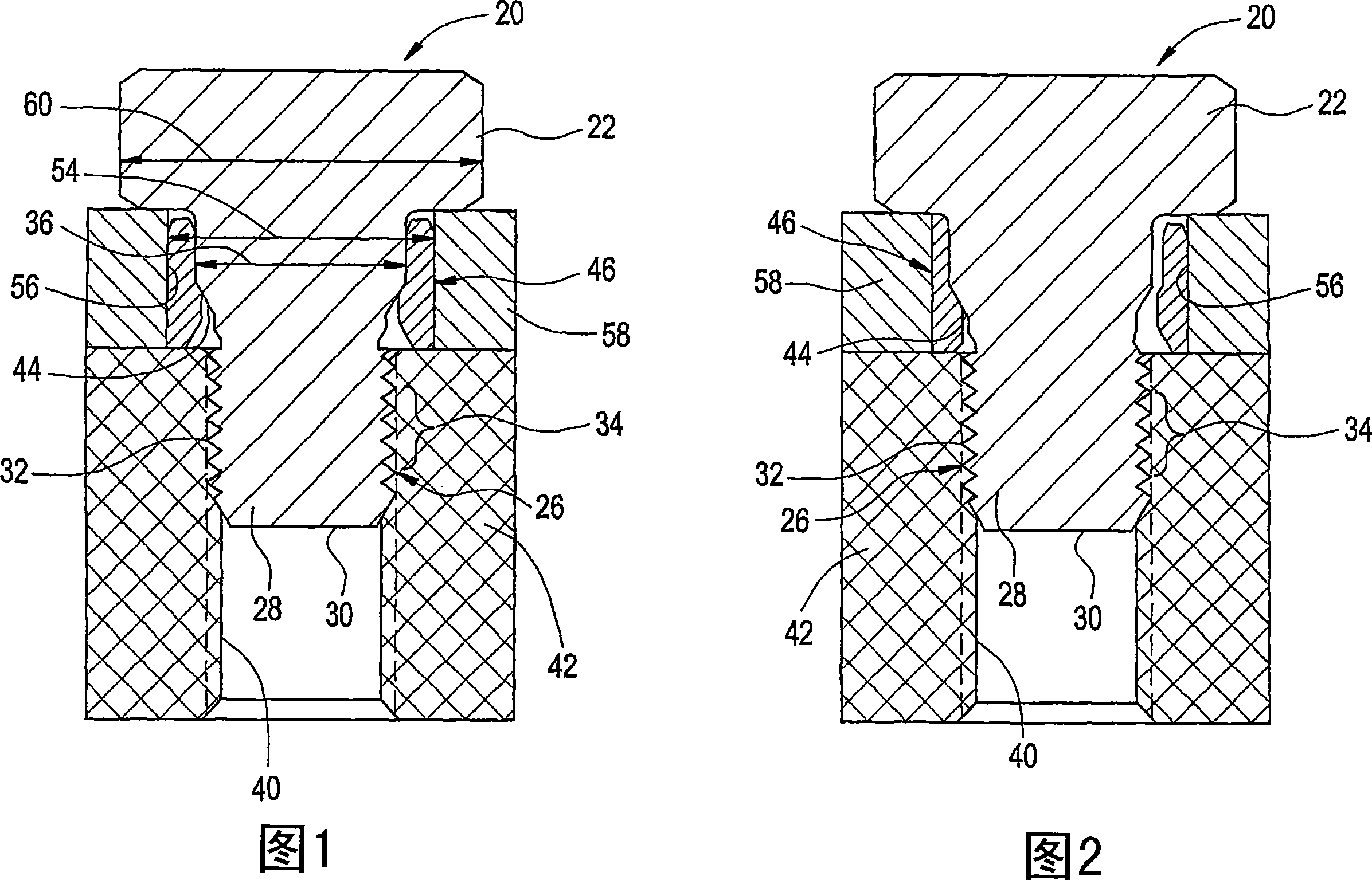
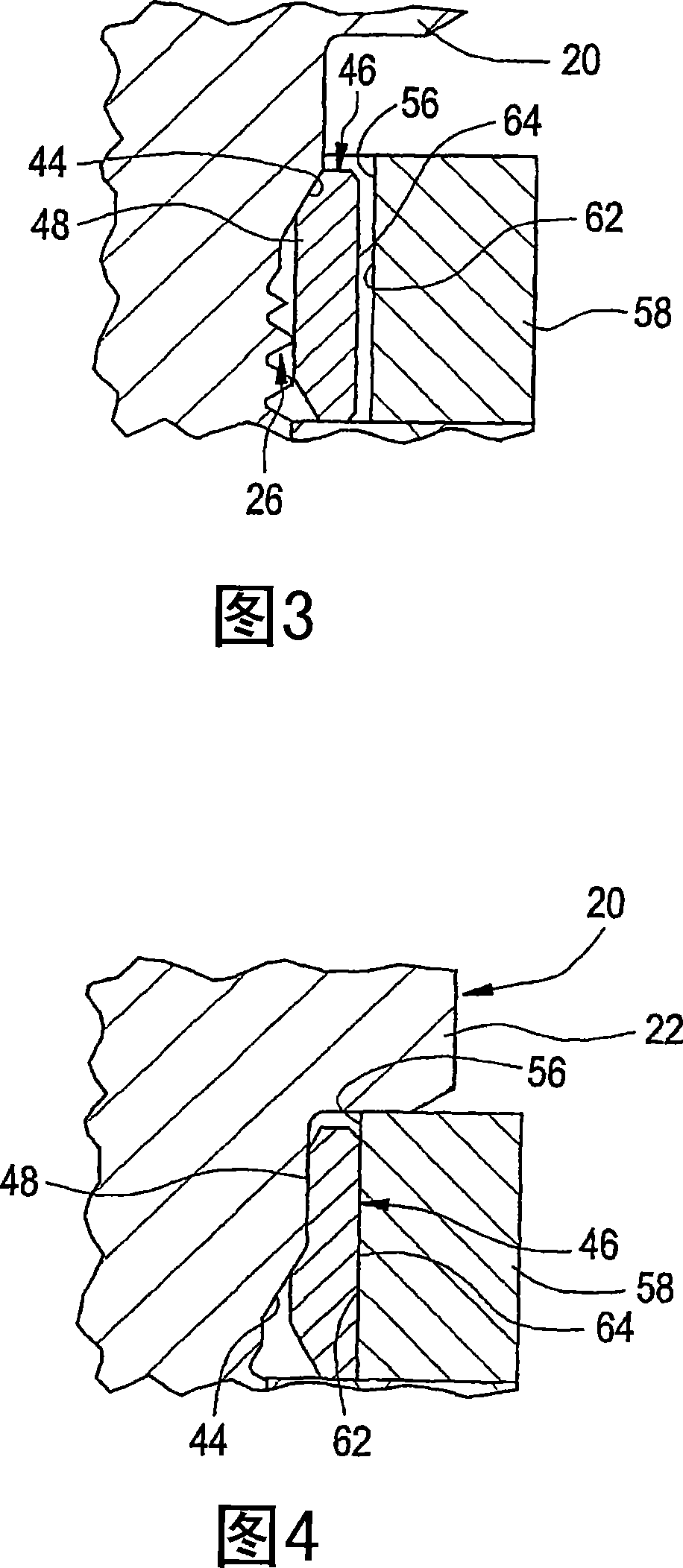
[0026] Such as figure 1 and figure 2 As shown, the bolted joint includes a bolt 20 having a head 22, which preferably has Figure 7 The hexagonal profile 24 is shown. Of course, the head 22 can also have other contours than hexagonal. Near the opposite end 30 of the bolt 20 , the threaded portion...


PUM


Abstract

A bolted joint which is formed by using a bolt having a tapered shoulder to cold form a deformable sleeve in order to provide a “zero-clearance” fit. Specifically, preferably a plurality of bolted joints are used to join a ring gear to a differential case. As the bolts are installed into the differential case and ring gear, tapered shoulders on the bolts dilate deformable sleeves until outer diameters of the sleeves contact internal walls of through holes in the differential case.

Description

technical field [0001] The present invention relates generally to bolting joints, and more particularly to zero clearance bolting joints, for example for joining ring gears to differential cases. Background technique [0002] One application that has been proposed for the use of bolted joints is the jointing of ring gears to differential cases. Normally, however, the bolted engagement prevents movement of the gears relative to the case. This is because the bolts are not able to generate enough tension to stop the gears from slipping, which would cause the bolts to back off and disengage. [0003] One existing method of engaging the ring gear to the differential case is to use a matching circular pattern of through holes on the differential case and tapered holes on the ring gear. This design places demands on the hole position tolerance performance of the manufacturing equipment. The problem, therefore, is the need to develop a method of securing the differential case to ...

Claims


Application Information

Patent Timeline
Patent Type & Authority Patents(China)
IPC IPC(8): F16B43/00
CPCF16B35/06F16B43/00Y10S411/969F16B4/004
Inventor 本杰明·N·朗
Owner ACUMENT INTPROP LLC
Features
  • R&D
  • Intellectual Property
  • Life Sciences
  • Materials
  • Tech Scout
  • Unparalleled Data Quality
  • Higher Quality Content
  • 60% Fewer Hallucinations
Learn More