Emulation test bench for vehicle operating of rail locomotive based on differentia transmission

A technology of differential transmission and vehicle operation, applied in the direction of railway vehicle testing, etc., can solve the problems of complex structure, occupying a large space, and inconvenient dynamic parameter detection.

Inactive Publication Date: 2009-11-25
SOUTHWEST JIAOTONG UNIV
View PDF0 Cites 21 Cited by
  • Summary
  • Abstract
  • Description
  • Claims
  • Application Information

AI Technical Summary

Problems solved by technology

The disadvantage of using the circular track method is that it needs to build a test line, which takes up a lot of space, and it is very inconvenient or even impossible to detect some dynamic parameters of th

Method used


Image

  • Emulation test bench for vehicle operating of rail locomotive based on differentia transmission
  • Emulation test bench for vehicle operating of rail locomotive based on differentia transmission
  • Emulation test bench for vehicle operating of rail locomotive based on differentia transmission

Examples


specific Embodiment approach

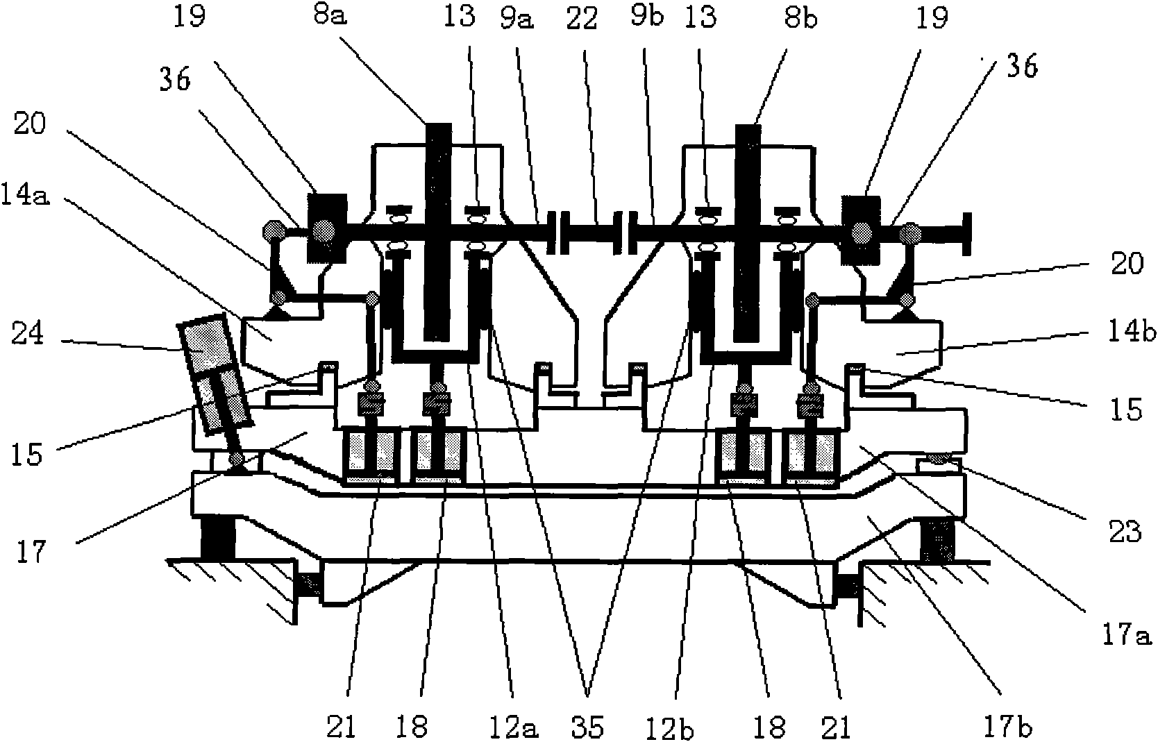
[0039] figure 1 , figure 2 and Figure 5 Shown, a kind of specific embodiment of the present invention is:

[0040] A railway locomotive vehicle operation simulation test bench is composed of several test units, and the specific structure of each test unit is:

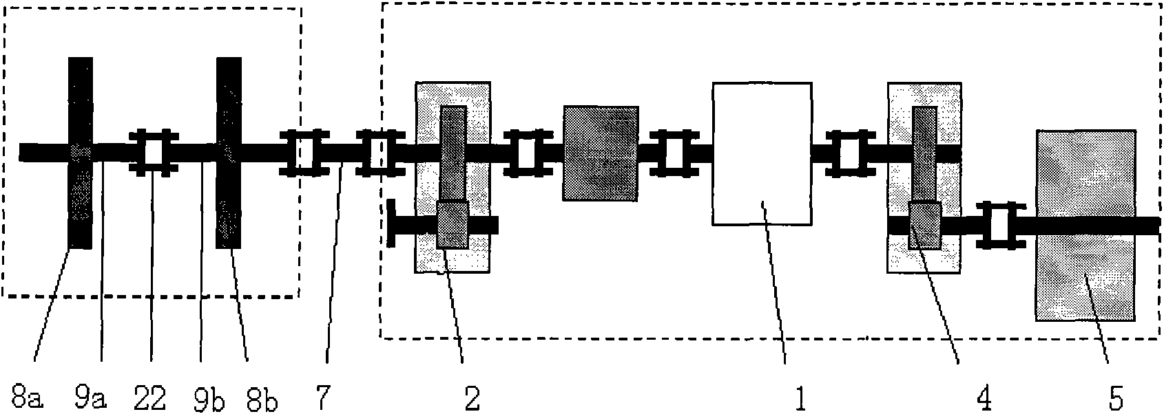
[0041] The driving mechanism is connected with the right roller shaft 9b through the cardan shaft 7, and the left roller shaft 9a is connected with the right roller shaft 9b through a floating coupling 22; or the left roller shaft 9a is connected with the differential transmission mechanism of the driving mechanism; The rollers 8a, 8b are installed on the left and right roller shafts 9a, 9b respectively.

[0042] Left and right roller shafts 9a, 9b are supported on left and right U-shaped frames 12a, 12b by bearings 13 respectively; Right roller seat 14a, 14b inner wall; Left and right roller seat 14a, 14b are all installed on the base 17.

[0043] The bottoms of the left and right U-shaped frames 12a, 12b are co...
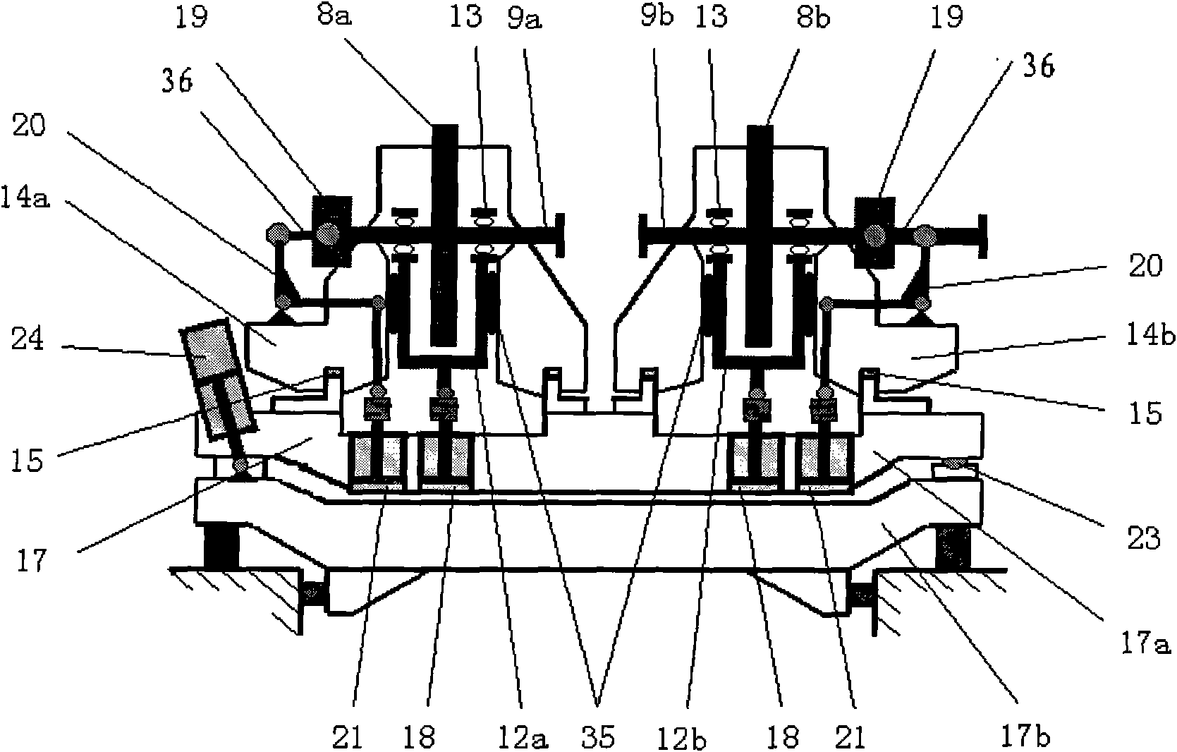
Embodiment 2

[0053] image 3 , Figure 4 and Figure 5 Shown, this embodiment is basically the same as Embodiment 1, except that the floating coupling (22) between the left roller shaft (9a) and the right roller shaft (9b) is removed. Instead, the left roller shaft 9a is connected to the differential transmission mechanism of the drive mechanism; the drive mechanism is composed of: the motor 1 is connected to the synchronous shunt gear box 2', and the synchronous shunt gear box 2' is directly output in the same direction as the motor 1 shaft The end is connected with the right roller shaft 9b through the cardan shaft 7; the synchronous output end perpendicular to the direction of the motor shaft is docked with the synchronous output end of the synchronous shunt gearbox 2' of the adjacent test unit, and the vertical output end perpendicular to the direction of the motor shaft It is connected with the left roller shaft 9a through a differential transmission mechanism. The composition of t...


PUM


Abstract

An emulation test bench for vehicle operating of rail locomotive based on differentia transmission is composed of a plurality of test units each having the structure as follows: a driving mechanism is connected with a left and a right rollers, which are supported on a left and a right U-shaped frames which are mounted on the inner walls of the left and right roller bases through vertical linear bearings on the side walls thereof; the left and right roller bases are mounted on a base, on which the bottoms of the left and right U-shaped frames are connected through a vertical hydraulic vibration exciter; the external ends of the left and right roller shafts are connected with a transverse hydraulic vibration exciter which is fixed on the base; and the left and right roller bases are mounted on the base through a revolving bearing and is connected with a revolving vibration exciter thereof. The test bench can simulate the motion of locomotives on railways, the smooth operation state of locomotives, perturbations on the lines irregular vertically and transversely and bended laterally and transversely, and the moving sate of locomotives on curved lines.

Description

[0001] This application is a divisional application of No. 200610022732.6 patent application titled "Railway Locomotive Vehicle Operation Simulation Test Bench" and filed on December 31, 2006. The divisional application was carried out according to the suggestion of the second examination opinion notice of the original application. In order to avoid being indistinguishable from the same name as the original application, the applicant changed the name of this divisional application to "based on the differential transmission mechanism". Railway rolling stock operation simulation test bench". technical field [0002] The invention relates to a railway locomotive vehicle running simulation test platform. Background technique [0003] The dynamic performance of railway rolling stock is the most important factor that directly affects the quality of train operation (including safety and reliability, fast and convenient, high efficiency and energy saving, stability and comfort, etc....

Claims


Application Information

Patent Timeline
IPC IPC(8): G01M17/08
Inventor 张卫华马世骏马启文周文祥黄丽湘
Owner SOUTHWEST JIAOTONG UNIV
Why Eureka
Try Eureka