
Cell cover clamping and locking structure

A battery cover and lock technology, which is applied to the telephone structure, structural parts, battery pack components, etc., can solve the problems of inconvenient operation, laborious disassembly and assembly, damage to the battery cover, etc., and achieve the effect of labor-saving operation.

Inactive Publication Date: 2009-11-25
SHENZHEN FUTAIHONG PRECISION IND CO LTD
View PDF0 Cites 3 Cited by
  • Summary
  • Abstract
  • Description
  • Claims
  • Application Information

AI Technical Summary

Problems solved by technology

[0004] Although this type of battery cover is tightly and firmly combined with the body after installation, it is laborious to disassemble and inconvenient to operate, and excessive force will damage the battery cover, and even cause damage to the portable electronic device in more serious cases

Method used


Image

  • Cell cover clamping and locking structure
  • Cell cover clamping and locking structure
  • Cell cover clamping and locking structure

Examples


Embodiment Construction

[0014] The invention discloses a locking structure of a battery cover, which is applied to portable electronic devices such as mobile phones. In this preferred embodiment, the mobile phone is taken as an example for illustration.

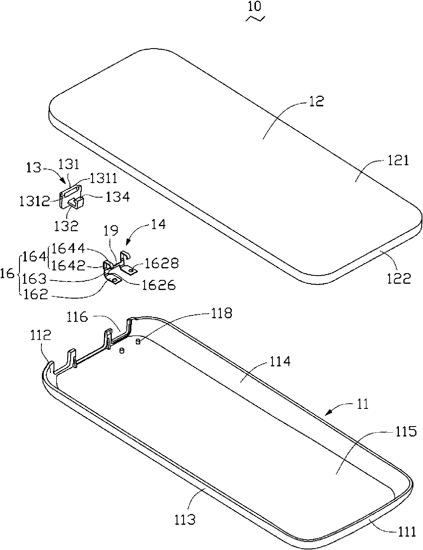
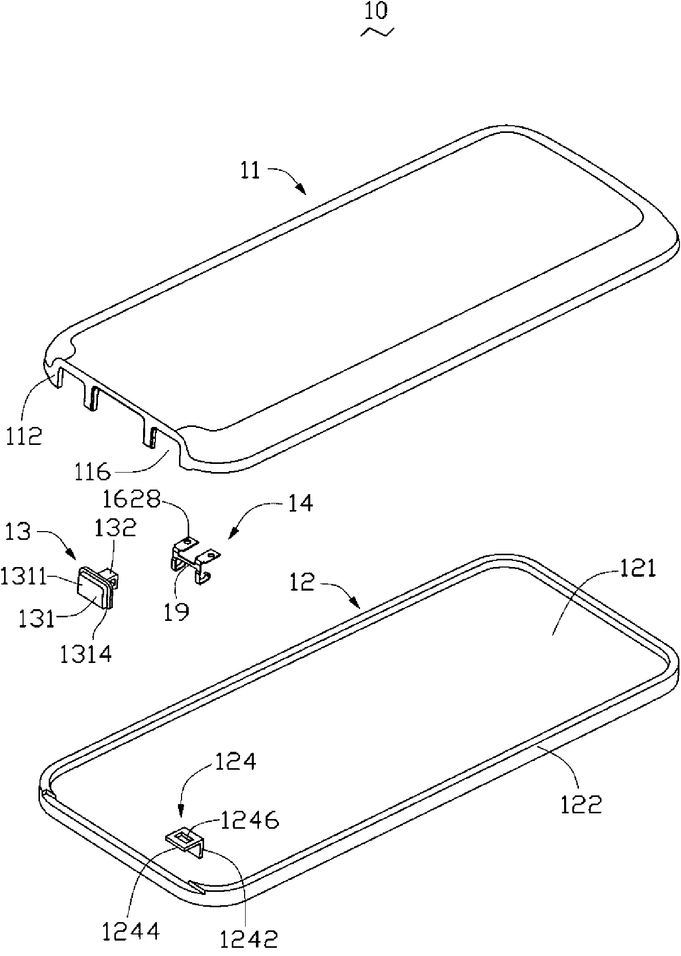
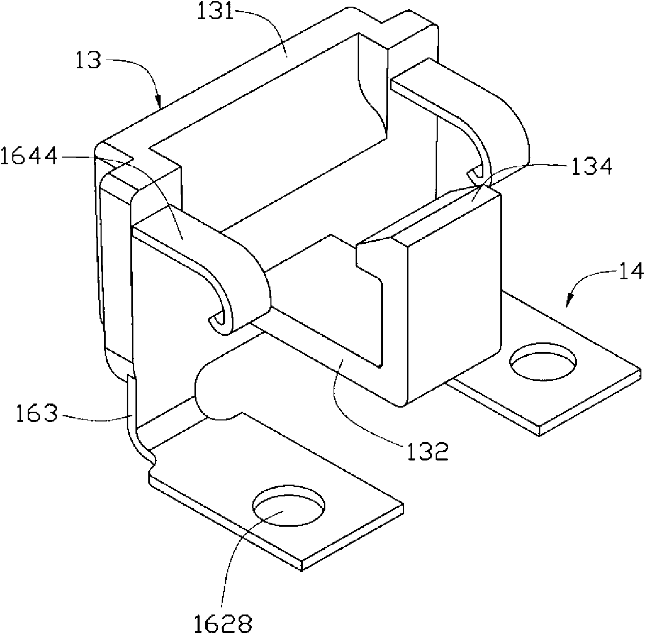
[0015] see figure 1 and figure 2 , The battery cover locking structure 10 of the present invention includes a body 11 , a battery cover 12 , a button 13 and a reset piece 14 .

[0016] The body 11 has a top wall 111 , a bottom wall 112 opposite to the top wall 111 , a left side wall 113 and a right side wall 114 connecting the top wall 111 and the bottom wall 112 . The top wall 111, the bottom wall 112, the left side wall 113 and the right side wall 114 encircle a rectangular accommodating groove 115 for accommodating electronic components such as batteries (not shown) and circuit boards of mobile phones (not shown in the figure). Show). A rectangular notch 116 is formed through the bottom wall 112 . The notch 116 communicates with the receivin...


PUM


Abstract

The invention provides a cell cover clamping and locking structure, which comprises a machine body, a cell cover, a button and a reset element; the cell cover is provided with a buckle element; the button is provided with a jaw; and one end of the reset element is fixed and supported on the machine body, and is embedded in the button, so that the jaw is detachably clamped on the buckle element. The cell cover clamping and locking structure provides elasticity and restoring force for the button through the reset element; and when the cell cover is disassembled, only the button is needed to be pressed slightly to separate the jaw and the buckle element so as to achieve the aim of unlocking.

Description

technical field [0001] The invention relates to a locking structure of a battery cover, in particular to a locking structure of a battery cover applied to portable electronic devices such as mobile phones. Background technique [0002] Mobile phones and personal digital assistants (Personal Digital Assistant, PDA) and other portable electronic devices are increasingly widely used, and the batteries that provide energy for portable electronic devices have to be replaced due to energy consumption. In order to make the battery easy to install, people have designed Many battery cover snap-lock structures. [0003] The locking structure of the battery cover of the existing portable electronic device is mostly fixed on the body by a hook and a buckle structure, that is, a pair of hooks are set at one end of the battery cover, and a locking pin is set at the other end, correspondingly at one end of the body. A pair of card slots are set, and a lock hole is set at the other end. W...

Claims


Application Information

Patent Timeline
Patent Type & Authority Applications(China)
IPC IPC(8): H01M2/10H05K5/02H05K5/03G06F1/16G06F1/26H04M1/02H01M50/247H01M50/262H01M50/271
CPCH04M1/0262
Inventor 申志云张智强
Owner SHENZHEN FUTAIHONG PRECISION IND CO LTD
Learn More