
Light source packaging structure

A packaging structure and light source technology, applied in the direction of light source, electric light source, point light source, etc., can solve problems such as not being as expected, and the device is not popular

Inactive Publication Date: 2010-01-13
IND TECH RES INST
View PDF0 Cites 2 Cited by
  • Summary
  • Abstract
  • Description
  • Claims
  • Application Information

AI Technical Summary

Problems solved by technology

However, since the LED itself is not an ideal point light source, the light emitted from the LED will not be modulated by the micro-groove structure as expected
In addition, the device for making the micro-groove structure is not popular

Method used


Image

  • Light source packaging structure
  • Light source packaging structure
  • Light source packaging structure

Examples


Embodiment Construction

[0085] In order to have a further understanding and understanding of the characteristics, purpose and functions of the present invention, the relevant structure and design concept of the system of the present invention are described below, and the detailed statements are as follows:

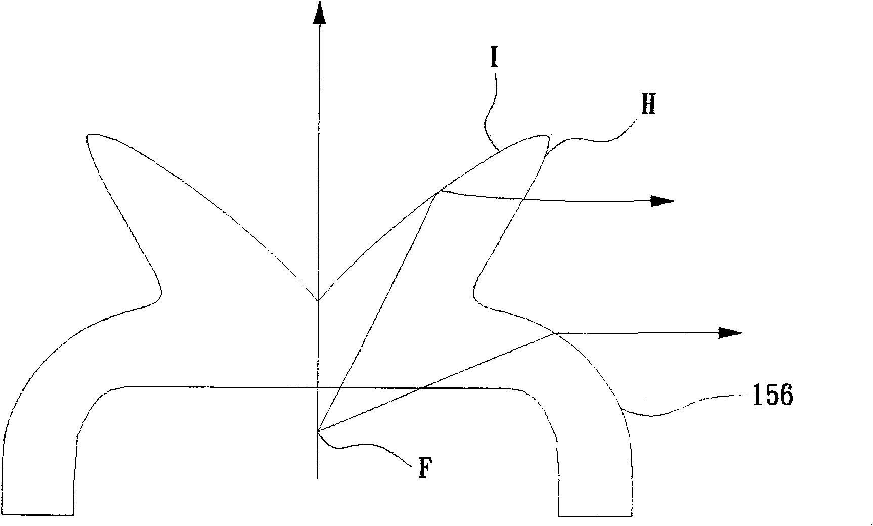
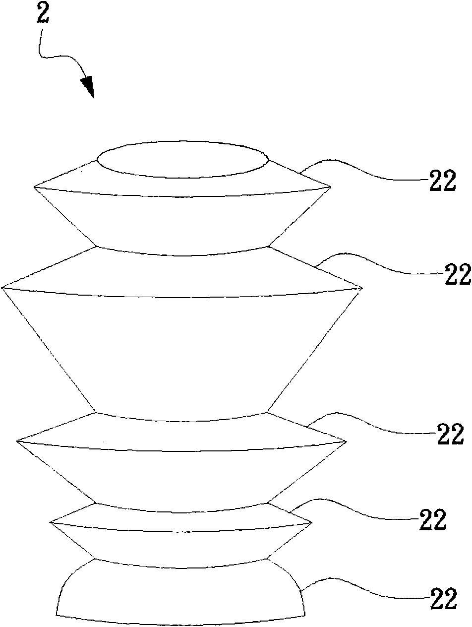
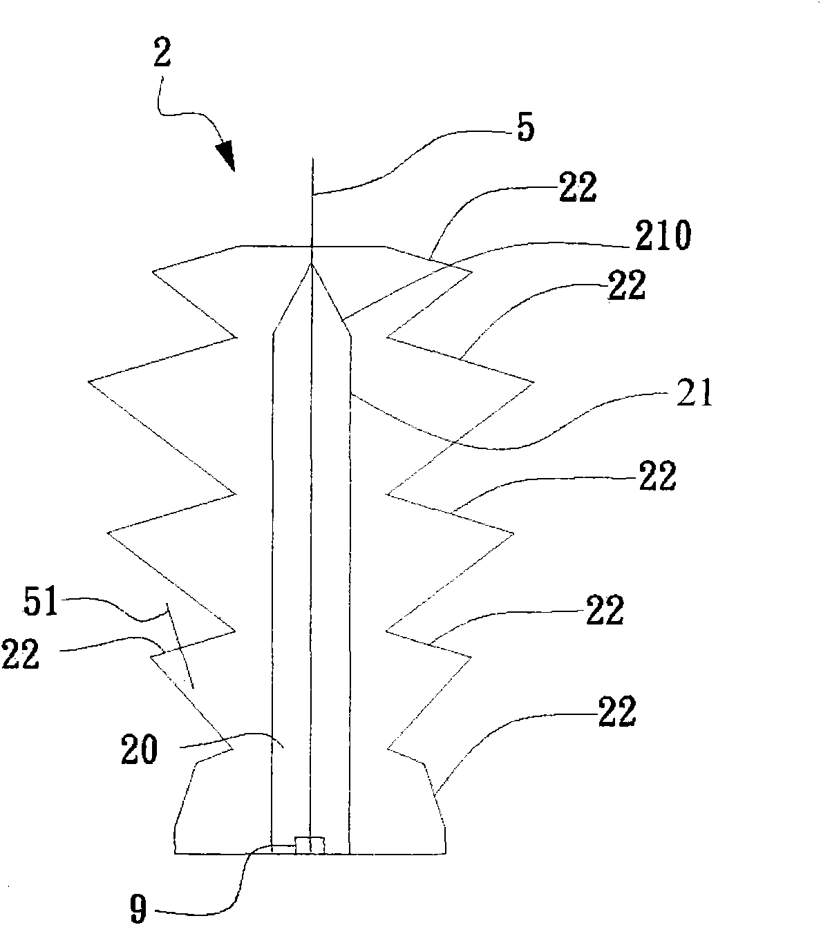
[0086] see Figure 2A as well as Figure 2B As shown, the figure is a perspective view and a schematic cross-sectional view of the first preferred embodiment of the light source packaging structure of the present invention. The light source packaging structure 2 includes: a light source accommodating portion 20 , a first refraction surface 21 and at least one second refraction surface 22 . The light source accommodating portion 20 can accommodate a light source body 9 . The first refraction surface 21 covers the light source body 9 to receive the light generated by the light source body 9 to form a first refraction light. The top of the first refraction surface 21 has a tapered surface 210 . T...


PUM

PropertyMeasurementUnit
Angleaaaaaaaaaa

Abstract

The invention relates to a light source packaging structure comprising a light source accommodating part, a first refracting surface and at least one second refracting surface, wherein the light source accommodating part is used for accommodating a light source body, the first refracting surface can receive light generated by the light source body to form first refract light, and the upper end of the first refracting surface is provided with a refracting structure; the second refracting surface is used for receiving the first refract light to form emergent light to leave the light source packaging structure, and an included angle is formed between a normal vector of the second refracting surface and a central axis of the light source packaging structure. The invention uses the structure to extend various packaging structures to increase light deviation effect. The light source packaging structure can be used as a light emitting diode packaging structure to refract light transmitted by a light emitting diode many times and deviate to a large-angle direction, and the light source sealing structure can be applied to the field of a plane light source to supply multiple purposes.

Description

[0001] This application is a divisional application, parent application number: 200610082825.8, application date: June 13, 2006, invention name: light source packaging structure. technical field [0002] The present invention relates to a packaging structure, in particular to a light source packaging structure which can generate large-angle deflection by making light refracted multiple times. Background technique [0003] In the structure of the current large-size backlight module of the display, a cold cathode tube (Cold Cathode Fluorescent Lamp, CCFL) is mainly used as the backlight source to illuminate the liquid crystal panel. However, with the progress of light-emitting diode technology, it is an irresistible trend to use light-emitting diodes as backlight sources for large-size liquid crystal displays. Compared with cold-cathode tubes, light-emitting diodes have the following advantages: (1) Light-emitting diodes are smaller than cold-cathode tubes and are not easily b...

Claims


Application Information

Patent Timeline
IPC IPC(8): F21S2/00F21V19/00F21V5/00F21V13/00H01L33/00F21Y101/02F21V5/04
Inventor 孙翊庭姚柏宏黄珩春许修真
Owner IND TECH RES INST
Learn More