
Touch control panel

A technology of touch panels and substrates, which is applied in the direction of instruments, electrical digital data processing, static electricity, etc., can solve the problems of touch circuit damage, yield reduction, etc., and achieve good electrostatic discharge protection effect

Active Publication Date: 2010-02-24
AU OPTRONICS CORP
View PDF0 Cites 50 Cited by
  • Summary
  • Abstract
  • Description
  • Claims
  • Application Information

AI Technical Summary

Problems solved by technology

[0003] Regardless of the integrated / built-in touch panel or the external touch panel, they all face the problem of yield reduction caused by electrostatic discharge in manufacturing, and the integrated / built-in touch panel is more serious.
For example, most of the current integrated / built-in touch panels are made on one surface of the substrate first to make the touch circuit, and then make a color filter film on the other surface of the substrate. After making the color filter At the same time as the thin film, the touch circuit is often damaged by electrostatic discharge
In addition, when the user touches the integrated / built-in touch panel and the external touch panel with a finger, electrostatic discharge may also occur, which may cause damage to the touch circuit

Method used


Image

  • Touch control panel
  • Touch control panel
  • Touch control panel

Examples


no. 2 example

[0070] Image 6 It is a schematic diagram of the touch panel according to the second embodiment of the present invention. Please refer to Image 6 In the touch panel 200 of the present embodiment, the second sensing series 230 arranged in the same row can be divided into two second sensing series 230, where the second sensing series 230 on the left and the distribution The sensing signal transmission line 250 on the left is electrically connected, and the second sensing series 230 on the right is electrically connected with the sensing signal transmission line 250 distributed on the right. In detail, the second sensing series 230 are divided into two groups, and are electrically connected to the two groups of sensing signal transmission lines 250 respectively.

[0071] Figure 7A to Figure 7C for Image 6 A partial enlarged schematic diagram of the middle D area. Please refer to Image 6 versus Figure 7A The touch panel 200 of this embodiment includes a substrate 210, a plurali...


PUM


Abstract

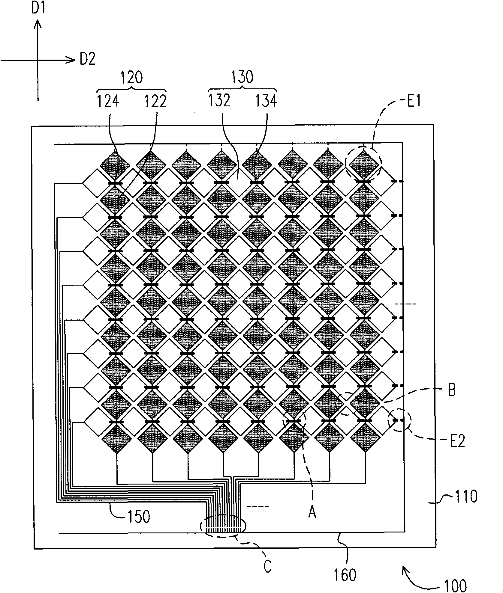
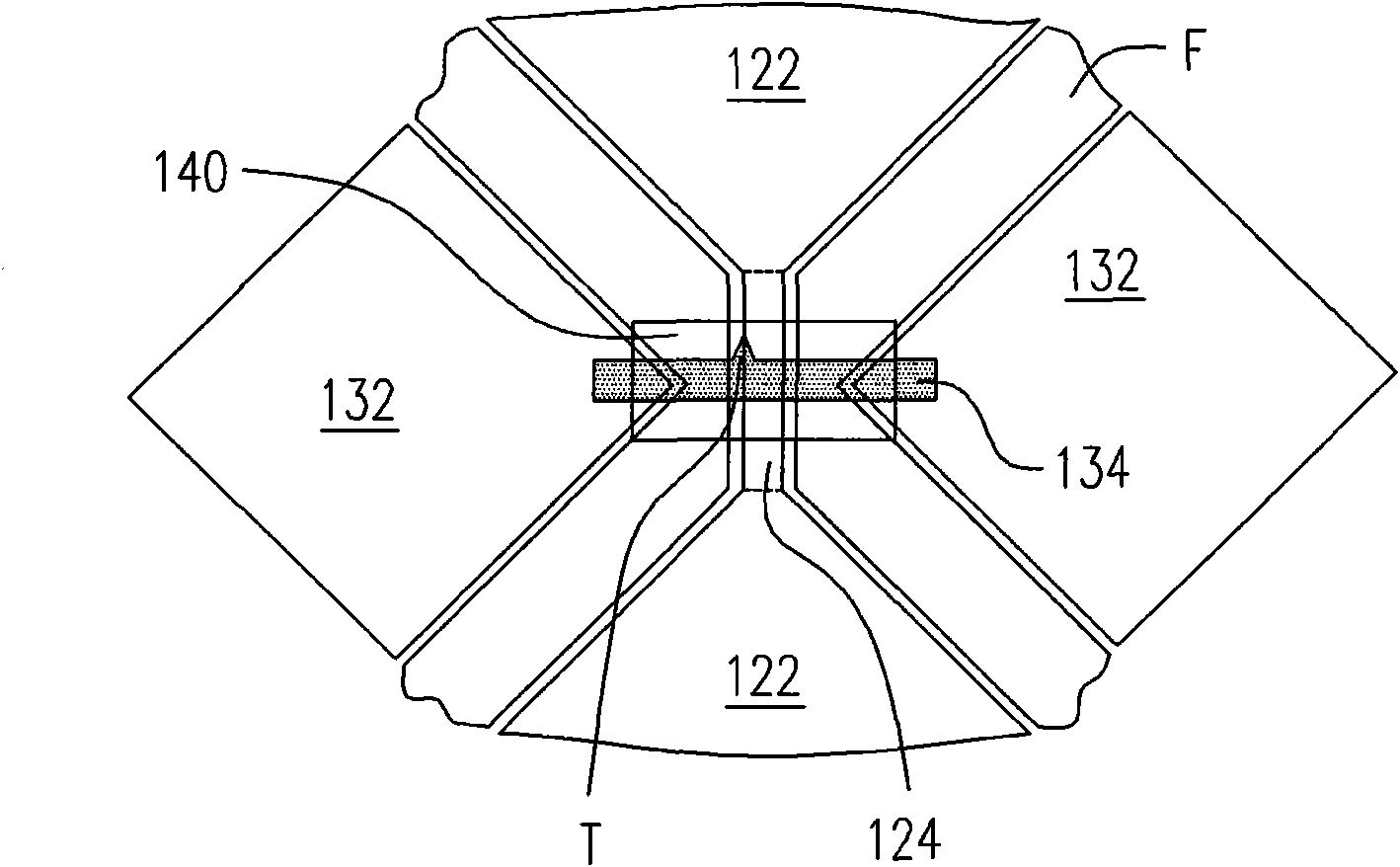
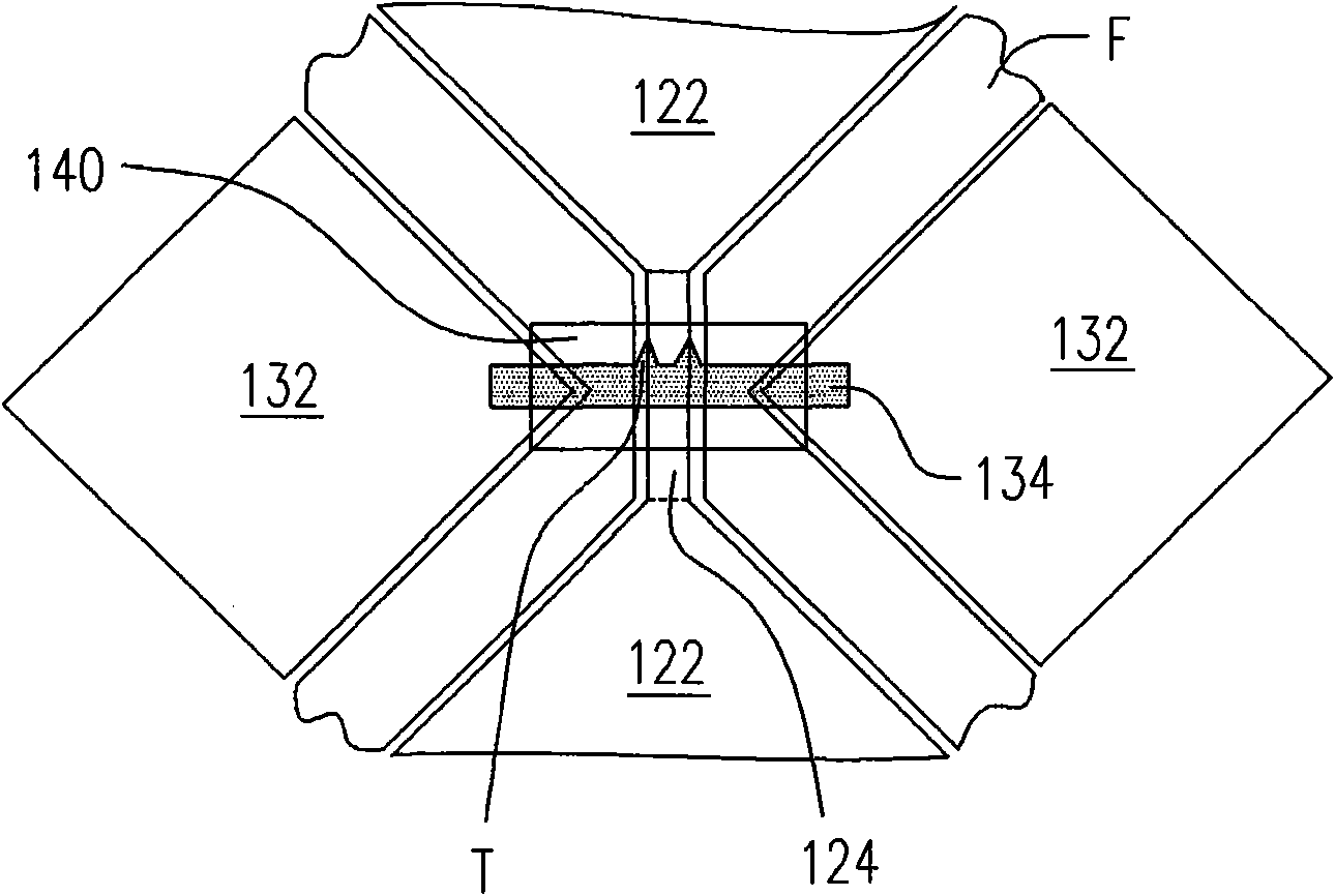
A touch control panel comprises a substrate, a plurality of first sensing serials and a plurality of second sensing serials, wherein the first sensing serials are configured on the substrate, each ofthe first sensing serials extends along the first direction and electrically insulated and comprises a plurality of sensing pads and a plurality of bridging parts each of which is electrically connected between two adjacent first sensing pads respectively; the second sensing serials are configured on the substrate, wherein each of the second sensing serials extends along the second direction and electrically insulated and comprises a plurality of sensing pads and a plurality of bridging parts each of which is electrically connected between two adjacent second sensing pads respectively, each ofthe second bridging parts is staggered with each of the first bridging parts, and at least one of the second bridging part is provided with at least one static discharge tip. Due to use of static discharge tip connected with the sensing serials, the inventive touch control panel has good static discharge protection.

Description

Technical field [0001] The present invention relates to a touch panel, and in particular to a touch panel with good capability of ESD protection. Background technique [0002] Touch panels are roughly classified into resistive touch panels, capacitive touch panels, optical touch panels, acoustic touch panels, and electromagnetic touch panels according to their different sensing methods. Since the capacitive touch panel has the advantages of fast response time, good reliability, and high durability, the capacitive touch panel has been widely used in electronic products. According to different structures and manufacturing methods, capacitive touch panels can be roughly divided into two types: external type and integrated type / in cell. Externally attached capacitive touch panels usually first fabricate the sensing series on a substrate, and then attach the fabricated substrate to the outer surface of the display. Obviously, the external The sticky touch panel will have a certain t...

Claims


Application Information

Patent Timeline
Patent Type & Authority Applications(China)
IPC IPC(8): G06F3/041H05F3/04
Inventor 林育全刘胜发郭峻廷李信宏张维仁陈佩瑜邱钰梅马玫生郑国兴
Owner AU OPTRONICS CORP
Learn More