
Method for operating a cleaning apparatus of a printing press

A technology for cleaning devices and printing machines, applied to printing machines, general parts of printing machinery, printing, etc., can solve the problems of not being able to clean thoroughly, not being able to make practical and beneficial contributions, and achieve the effect of strengthening contact

Inactive Publication Date: 2013-01-09
HEIDELBERGER DRUCKMASCHINEN AG
View PDF3 Cites 1 Cited by
  • Summary
  • Abstract
  • Description
  • Claims
  • Application Information

AI Technical Summary

Problems solved by technology

This method, while allowing for quick cleaning of the brush rolls, does not allow for thorough cleaning
[0005] For the solution of this problem, EP 0520305 A1 has not been able to make practical and beneficial contributions

Method used


Image

  • Method for operating a cleaning apparatus of a printing press
  • Method for operating a cleaning apparatus of a printing press

Examples


Embodiment Construction

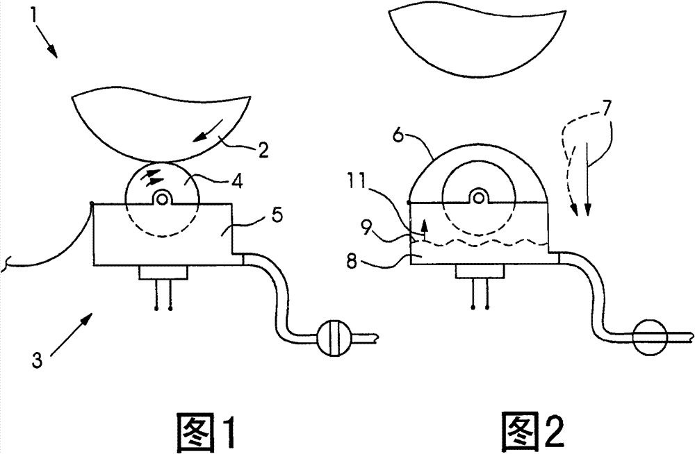
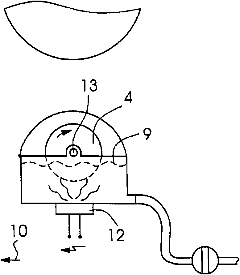
[0027] figure 1 A partial view of a printing press 1 is shown in . The printing press 1 is an offset lithographic printing press for printing sheets. The detail shows the components of the varnishing device of the printing press 1 . The varnishing device comprises a cylinder 2 which carries a blanket for full-surface varnishing or a flexographic printing plate for partial varnishing. A cleaning device 3 is assigned to the drum 2 . During the cleaning of the cylinder 2 , the brush roller 4 of the cleaning device 3 rests against this cylinder, or more precisely against the blanket or flexographic printing plate. The brush roller 4 is partially immersed in the tank 5 , with which the brush roller 4 forms a structural unit that is movable towards and away from the drum 2 .

[0028] figure 2 It is shown that the cover 6 of the tub 5 is closed in order to cover the opening of the tub 5 directed toward the drum 2 and the part of the brush roller 4 protruding from the tub 5 . T...


PUM


Abstract

A method for operating a cleaning apparatus, having a trough and a brush disposed in the trough, in a printing press, includes first, second and third steps. In the first step, a cylinder of the printing press is cleaned by the cleaning apparatus, with the brush bearing against the cylinder. In the second step, the brush is moved away from the cylinder, and a level of a liquid in the trough is changed, resulting in the liquid being brought into contact with the brush. In the third step, the brush is cleaned by the liquid in the trough. A printing press for carrying out the method is also provided.

Description

technical field [0001] The invention relates to a method for operating a cleaning device of a printing press. Background technique [0002] The invention arises from the background that printing press cylinders, such as plate cylinders, blanket cylinders or impression cylinders, are cleaned by a cleaning device. These cleaning devices often include brush rolls. Such brush rollers become soiled when cleaning the cylinder and must therefore themselves be cleaned from time to time. Cleaning of brush rolls can be done outside or inside the printing press. [0003] In DE 10213647 B4 it is described that the brush rollers are cleaned outside the printing press. In this case, the cleaning device is removed from the printing press together with the brush roller and placed into the cleaning tank. The cleaning tank is equipped with a sonotrode which acts on the cleaning liquid in order to enhance its action. The disadvantage is that it takes a lot of time to remove the cleaning d...

Claims


Application Information

Patent Timeline
IPC IPC(8): B41F35/00
CPCB41P2235/23B41F35/00
Inventor S·巴里斯R·霍夫曼P·罗特B·西茨曼M·乌伊莱因
Owner HEIDELBERGER DRUCKMASCHINEN AG
Learn More