Wave power plant

A wave power generation, wave technology, applied in the direction of ocean energy power generation, engine components, machines/engines, etc., can solve problems such as difficult continuous rotation

Inactive Publication Date: 2015-06-24
WELLO
View PDF6 Cites 1 Cited by
  • Summary
  • Abstract
  • Description
  • Claims
  • Application Information

AI Technical Summary

Problems solved by technology

It is difficult to efficiently convert this reciprocating motion into continuous rotary motion

Method used


Image

  • Wave power plant
  • Wave power plant
  • Wave power plant

Examples


Embodiment Construction

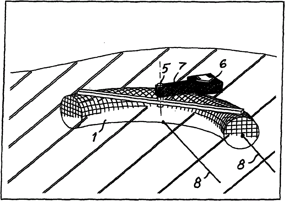
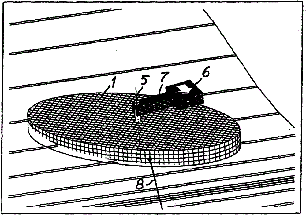
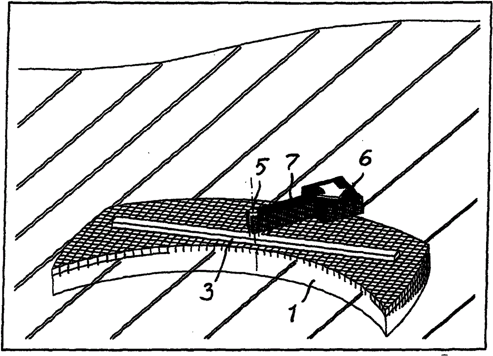
[0016] Figure 1-4 What is common among the embodiments is that the buoy or pontoon 1 is designed asymmetrically with respect to the direction in which the waves are advancing, so that the buoy or pontoon 1 can move itself out of the way with respect to the buoyancy of the continuously advancing waves in said direction. in rotary motion. exist Figure 1-4 , the double line shows the orientation of the platinum top. A long line 8 anchors the buoy or buoy 1 at a predetermined angular position (usually longitudinally) in the direction of travel of the sea wave. Such anchoring generally keeps the buoy or buoy 1 in its angular position regardless of changes in the direction of the waves. exist figure 1 , 3 In the case of and 4, the buoy or buoy 1 is curved, more specifically in the shape of a banana or croissant. exist figure 1 In a preferred embodiment, the buoy or pontoon 1 is circular or elliptical in cross-section at least in its water-surrounding portion. Thus, there w...


PUM


Abstract

The invention relates to a wave power plant, comprising at least one float or pontoon (1) or a plurality of interconnected floats or pontoons (2). The float or pontoon (1) is shaped or the interconnected floats or pontoons (2) are disposed asymmetrically relative to the advancing direction of waves, such that the float or pontoon (1) or a member (3) linking the interconnected floats or pontoons is set in a gyrating motion in response to the buoyancy of a succession of waves advancing in said direction. The wave power plant includes elements (5, 6, 7; 9, 10) for converting the gyrating motion into a rotational motion for power take-off.

Description

technical field [0001] The invention relates to an ocean wave power generation device, which comprises at least one float or pontoon or a plurality of connected floats or pontoons. [0002] In an alternative embodiment of the present invention, the ocean wave power generating device comprises anchored underwater blades. Background technique [0003] Document US-4,266,143 discloses a sea wave power plant with the aim of converting the side-by-side tilting of a pontoon into a rotational movement of two very heavy gravity wheels rotating in opposite directions. The pontoons are symmetrical and the gravity wheels are set in opposite orientations to ensure that only side-by-side tilting occurs. [0004] A problem with this and other known wave power devices is the random motion of the waves and fluctuations in wave size. It is difficult to efficiently convert this reciprocating motion into continuous rotational motion. Contents of the invention [0005] The object of the pre...

Claims


Application Information

Patent Timeline
Patent Type & Authority Patents(China)
IPC IPC(8): F03B13/14F03G7/08
CPCF05B2240/40F05B2250/70F03B13/20Y02E10/30F03B13/14F03G7/08
Inventor 海吉·帕金恩
Owner WELLO
Why Eureka
Try Eureka