
Linear type magnetic fluid traveling wave pump

A magnetic fluid, linear technology, applied in the direction of wave-generating pumps, pumps, non-variable pumps, etc., can solve the problems that the magnetic field effect of traveling waves has not been studied

Inactive Publication Date: 2010-06-02
HARBIN INST OF TECH
View PDF0 Cites 4 Cited by
  • Summary
  • Abstract
  • Description
  • Claims
  • Application Information

AI Technical Summary

Problems solved by technology

[0002] At present, the research on magnetohydrostatics is relatively in-depth, and gratifying achievements have been made in the application, but there is no research on the research on magnetohydrodynamics, especially on the effect of traveling wave magnetic field.
The prior art does not provide a linear magnetic fluid traveling wave pump for analyzing the movement law of the magnetic fluid caused by the traveling wave magnetic field

Method used


Image

  • Linear type magnetic fluid traveling wave pump
  • Linear type magnetic fluid traveling wave pump
  • Linear type magnetic fluid traveling wave pump

Examples


specific Embodiment approach 1

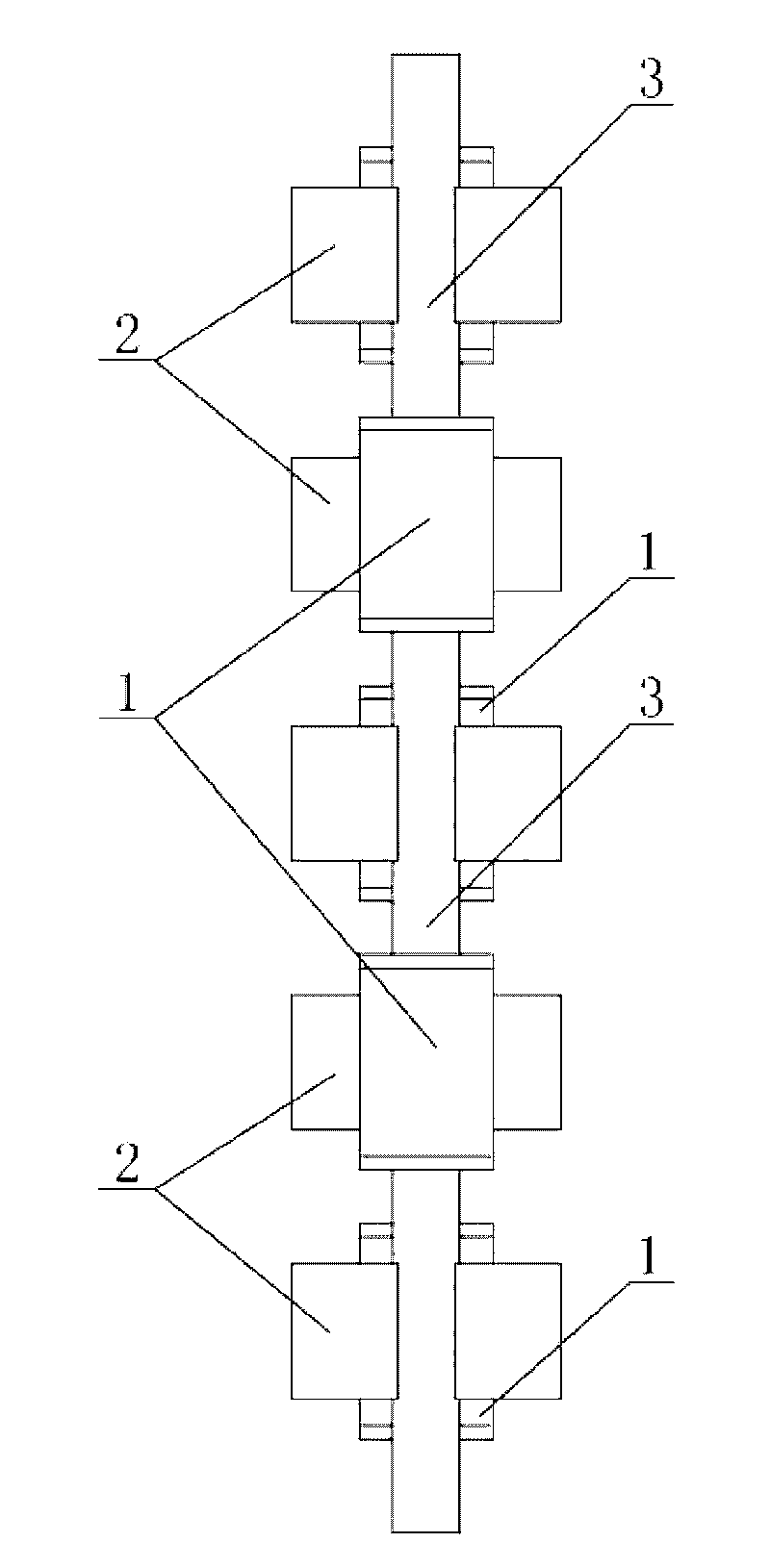
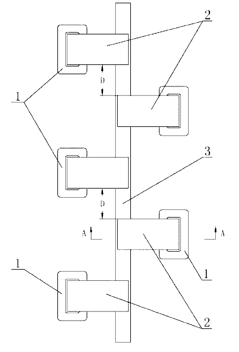
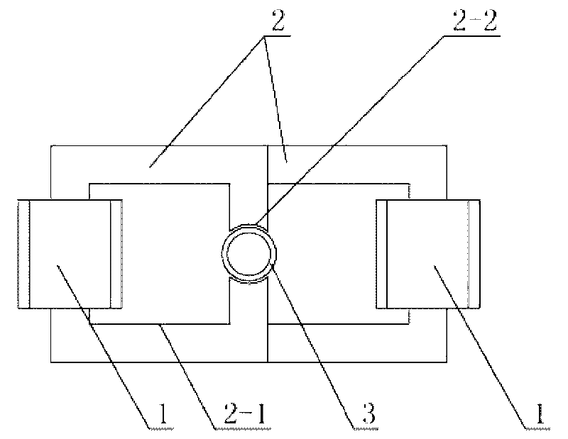
[0007] Specific implementation mode one: as Figure 1~4 As shown, the linear magnetic fluid traveling wave pump described in this embodiment is composed of three to ten energized coils 1, three to ten magnetic steel bodies 2 and conduits 3, and the middle part of the magnetic steel body 2 is along the There is a through hole 2-1 in the thickness direction, and a gap 2-2 connected with the through hole 2-1 is provided on the side wall of the magnetic steel body 2 along the thickness direction of the magnetic steel body 2. The number of energized coils 1 and the magnetic The number of steel bodies 2 is uniformly set, and a energized coil 1 is wound on the other side wall corresponding to the notch 2-2 on each magnetic steel body 2, and the conduit 3 passes through three to ten magnetic steel bodies in sequence 2, and two adjacent magnetic steel bodies 2 are arranged alternately on both sides of the conduit 3, and the distance D between two adjacent magnetic steel bodies 2 along ...

specific Embodiment approach 2

[0009] Specific implementation mode two: as Figure 1~4 As shown, the non-magnetic material in this embodiment is glass. With such a design, the glass can act as a magnetic barrier. Other components and connections are the same as those in the first embodiment.

specific Embodiment approach 3

[0010] Specific implementation mode three: as Figure 1~4 As shown, the non-magnetic permeable material in this embodiment is plastic. With such a design, the plastic can play the role of magnetic isolation. Other components and connections are the same as those in the first embodiment.


PUM


Abstract

The invention relates to a linear type magnetic fluid traveling wave pump, in particular to a magnetic fluid traveling wave pump. The invention solves the problem that the linear type magnetic fluid traveling wave pump for analyzing the movement law of the magnetic field of traveling wave on the magnetic fluid does not exist at present. The middle parts of magnetic steel bodies are provided with through holes along the direction of the thickness of the magnetic steel bodies; one side walls of the magnetic steel bodies are provided with breaches communicated with the through holes along the direction of the thickness of the magnetic steel bodies; the number of electrifying coils is set to be identical with the number of the magnetic steel bodies; the electrifying coil winds around the other side walls corresponding to the breach on each magnetic steel body; a pipe sequentially passes through the breaches of three to ten magnetic steel bodies; two adjacent magnetic steel bodies are staggered to be arranged at both sides of the pipe; the distance between the two adjacent magnetic steel bodies along the axis direction of the pipe is two to three times the thickness of the magnetic steel bodies; and the pipe is made of non-magnetic materials. The invention utilizes the principle of magnetic fluid dynamics to provide the linear type magnetic fluid traveling wave pum, and can validate the transport properties of magnetic fluid, thereby opening a new field of application of the magnetic fluid.

Description

technical field [0001] The invention relates to a magnetic fluid traveling wave pump, in particular to a linear magnetic fluid traveling wave pump used for analyzing the movement rule of the traveling wave magnetic field on the magnetic fluid. Background technique [0002] At present, the research on magnetohydrostatics is relatively in-depth, and gratifying achievements have been made in the application, but there is no research on the research on magnetohydrodynamics, especially on the effect of traveling wave magnetic field. The prior art does not provide a linear magnetic fluid traveling wave pump for analyzing the movement law of the magnetic fluid caused by the traveling wave magnetic field. Contents of the invention [0003] In order to solve the problem that there is no linear magnetic fluid traveling wave pump for analyzing the movement law of the magnetic fluid caused by the traveling wave magnetic field, the present invention further provides a linear magnetic f...

Claims


Application Information

Patent Timeline
IPC IPC(8): F04D35/00
Inventor 赵猛邹继斌胡建辉徐永向尚静赵博
Owner HARBIN INST OF TECH
Learn More