Short magnetic circuit structural cylindrical DC linear electric motor

A linear motor and short magnetic circuit technology, applied in the direction of magnetic circuit shape/style/structure, winding conductor shape/style/structure, electrical components, etc., can solve the problem of poor dynamic characteristics of motors, low air gap magnetic density, and iron core consumption Many problems, to achieve the effect of increasing the air gap magnetic flux density, reducing the secondary quality and magnetic flux leakage, and reducing the dosage

Inactive Publication Date: 2010-06-16
HARBIN INST OF TECH
View PDF0 Cites 9 Cited by
  • Summary
  • Abstract
  • Description
  • Claims
  • Application Information

AI Technical Summary

Problems solved by technology

[0004] The present invention solves the problem of poor dynamic characteristics of the motor due to the large mass of the mover when the existing motor has a long magnetic path, low air-gap magnetic density, large amount of iron core, heavy weight of the motor, and needs a movable secondary. A cylindrical DC linear motor with a short magnetic circuit structure is proposed

Method used


Image

  • Short magnetic circuit structural cylindrical DC linear electric motor
  • Short magnetic circuit structural cylindrical DC linear electric motor
  • Short magnetic circuit structural cylindrical DC linear electric motor

Examples


specific Embodiment approach 1

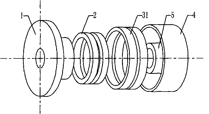
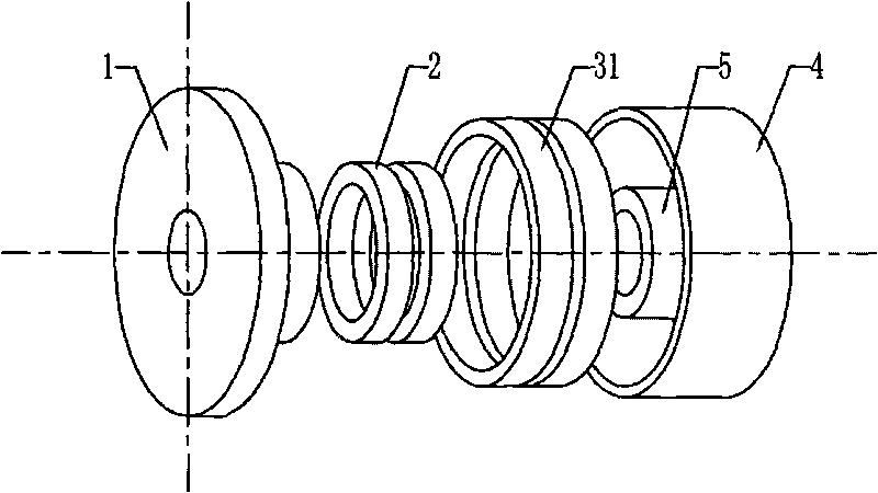
[0008] Specific implementation mode one: combine figure 1 , figure 2 , Figure 23 and Figure 24 Describe this embodiment, this embodiment is made up of primary, secondary and air gap;

[0009] The primary includes a winding support base 1 and an armature winding 2; the armature winding 2 is a single-phase winding, and the single-phase winding is composed of two coils, the two coils are connected in series, and the winding direction is opposite; the two coils Axially fixed on the winding support base 1; the secondary includes a permanent magnet and a magnetic yoke; the magnetic yoke includes an outer magnetic yoke 4 and an inner magnetic yoke 5, and the outer magnetic yoke 4 and the inner magnetic yoke 5 are circular Annular magnetic conducting yoke; the permanent magnet includes an outer secondary permanent magnet 31, and the outer secondary permanent magnet 31 is three annular permanent magnets; the three annular permanent magnets of the outer secondary permanent magnet...

specific Embodiment approach 2

[0010] Specific implementation mode two: combination figure 2 , Figure 4 , Figure 6 , Figure 8 , Figure 10 , Figure 12 , Figure 14 , Figure 16 , Figure 25 and Figure 26 This embodiment is described. The difference between this embodiment and the specific embodiment is that the two coils of the armature winding 2 are axially fixed on the outer wall of the boss of the winding support seat 1 or fixed on the end surface of the boss by using an insulating material. . Other compositions and connection methods are the same as those in Embodiment 1.

specific Embodiment approach 3

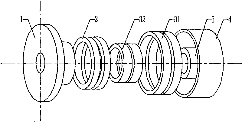
[0011] Specific implementation mode three: combination image 3 and Figure 4 Describe this embodiment, the difference between this embodiment and the specific embodiment is that the permanent magnet also includes an inner secondary permanent magnet 32, and the inner secondary permanent magnet 32 ​​is three annular permanent magnets, and the inner secondary permanent magnet 32 Closely fit on the outer wall of the circular inner magnetic yoke 5; the axial length of the inner secondary permanent magnet 32 ​​is the same as the axial length of the outer secondary permanent magnet 31, and the inner secondary permanent magnet 32 ​​is sequentially along the axial direction Radial magnetization, axial magnetization, radial magnetization; the magnetization direction of the radially magnetized permanent magnet in the inner secondary permanent magnet 32 ​​is the same as that of the radially magnetized permanent magnet in the outer secondary permanent magnet 31, The magnetization directi...


PUM


Abstract

The invention provides a short magnetic circuit structural cylindrical DC linear electric motor, relating to electric motor field and solving the problems that the existing electric motor has long magnetic circuit, low air gap magnetic density, large use amount of magnetic core and heavy electric motor, and that the dynamical property of the electric motor is poor due to large mass of rotor when needing dynamic secondary level. The two coils of the primary level in the invention are mutually connected in series and have opposite winding directions; the two coils are fixed on a winding supporting seat along the axial direction; the external magnetic guide yoke and the internal magnetic guide yoke in the secondary level are toroidal magnetic guide yokes; the permanent magnets in the secondary level are three toroidal permanent magnets; the permanent magnets are closely fit on the internal wall of the toroidal external magnetic guide yoke along the axial direction; the three permanent magnets are charged with magnetism sequentially along external radial direction, axial direction and internal radial direction; the permanent magnets and the primary level form external air gap; and the primary level and the internal magnetic guide yoke form internal air gap. The invention shortens the route of the magnetic flow of the permanent magnets, reduces secondary level mass and magnetic-leakage of the linear electric motor, enhances air gap magnetic density and improves the thrust output and dynamic response of the electric motor.

Description

technical field [0001] The invention relates to the field of electrical machines. Background technique [0002] The DC linear motor manufactured based on the principle of Ampere force has simple structure, small size, small thrust fluctuation, high reliability and high energy conversion efficiency, and is increasingly used in various linear motion control systems. Coupled with the characteristics of fast, smooth, no cogging, and no hysteresis response of DC linear motors, DC linear motors can be well used in servo control systems that require high speed, high acceleration, and high thrust response. [0003] Such as Figure 35 As shown, in the traditional structure of the cylindrical DC linear motor, the permanent magnet is cylindrical, radially magnetized, fixed on the inner side of a cylindrical outer conductive yoke, and the ring coil is fixed on the cylindrical coil On the supporting frame, the inner side of the annular coil is a cylindrical inner magnetic yoke, and the ...

Claims


Application Information

Patent Timeline
Patent Type & Authority Applications(China)
IPC IPC(8): H02K41/035H02K3/28H02K1/06
Inventor 寇宝泉李立毅潘东华张鲁张赫
Owner HARBIN INST OF TECH
Why Eureka
Try Eureka