Method and system for locking detection of phase-locked loop and phase-locked loop circuit

A lock detection, phase-locked loop technology, applied in the direction of electrical components, automatic power control, etc., can solve problems affecting the normal operation of the circuit, and achieve the effect of enhancing tolerance performance and maintaining stability

Active Publication Date: 2010-06-16
BEIJING VIMICRO ARTIFICIAL INTELLIGENCE CHIP TECH CO LTD
View PDF5 Cites 19 Cited by
  • Summary
  • Abstract
  • Description
  • Claims
  • Application Information

AI Technical Summary

Problems solved by technology

However, with this detection method of the lock detector, when there is an occasional large input clock jitter, the large clock jitter will increase the average value of the input clock frequency calculated within the preset time period, resulting in a phase-locked loop ju

Method used


Image

  • Method and system for locking detection of phase-locked loop and phase-locked loop circuit
  • Method and system for locking detection of phase-locked loop and phase-locked loop circuit
  • Method and system for locking detection of phase-locked loop and phase-locked loop circuit

Examples


Embodiment Construction

[0038] In order to make the object, technical solution and advantages of the present invention clearer, the present invention will be described in detail below with reference to the accompanying drawings and specific embodiments.

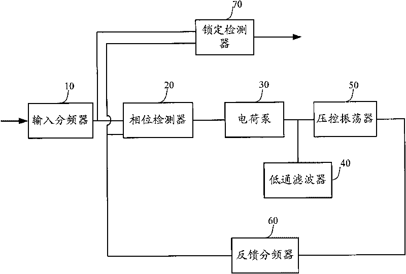
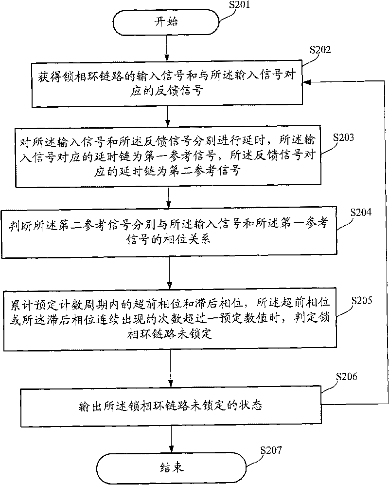
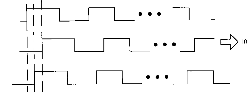
[0039] The method and system for phase-locked loop lock detection described in the specific embodiments of the present invention are determined by accumulating the dual-output phase relationship of the delay chain of the feedback clock relative to the input clock and the delay chain of the input clock within a predetermined counting period Large input jitter, and only when the cumulative occurrence of jitter in one direction exceeds a predetermined value, the phase-locked loop link will be determined to be in an unlocked state, so that the tolerance of the phase-locked loop link to a single input jitter is enhanced, which can Keep the output clock stable.

[0040] The method and system of specific embodiments of the present invention will be describ...


PUM


Abstract

The invention provides a method and a system for locking detection of a phase-locked loop and a phase-locked loop circuit. The method comprises the following steps: acquiring an input signal and a feedback signal; delaying the input signal and the feedback signal, wherein the corresponding time delay links of the input signal and the feedback signal are a first reference signal and a second reference signal respectively; judging the phase relations among the second reference signal, the input signal and the first reference signal, wherein the rising edge of the second reference signal is a leading phase before the rising edge of the input signal and the rising edge of the first reference signal and is a lag phase after the rising edge of the input signal and the rising edge of the first reference signal; and accumulating the leading phase and the lag phase in a predetermined counting period, and determining that the link of the phase-locked loop is not locked when the continuous occurrence number of the leading phase or the lag phase exceeds a predetermined numerical value. By adopting the double-output phase relation between the feedback clock delay link and the input clock delay link, the large input jitter is determined by the accumulation number, so the tolerance of the phase-locked loop to the input jitter is enhanced.

Description

technical field [0001] The invention relates to phase-locked loop circuit technology, in particular to a method, system and phase-locked loop circuit for phase-locked loop lock detection. Background technique [0002] Phase Locked Loop (PLL, Phase Locked Loop) is a frequency and phase synchronization technology realized by the principle of feedback control, and its function is to synchronize the clock output by the circuit with the external reference clock. When the frequency or phase of the reference clock changes, this change is detected and the output frequency is adjusted through an internal feedback system until the two are resynchronized. [0003] In the prior art, a phase-locked loop circuit includes an input frequency divider, a phase detector, a charge pump, a low-pass filter, a voltage-controlled oscillator, a feedback frequency divider and a lock detector. Wherein, when the phase-locked loop circuit is switched on and vibrates in a state with a stable frequency, ...

Claims


Application Information

Patent Timeline
IPC IPC(8): H03L7/08H03L7/085
Inventor 赵纲
Owner BEIJING VIMICRO ARTIFICIAL INTELLIGENCE CHIP TECH CO LTD
Why Eureka
Try Eureka