
Large-screen television with high brightness
A large-screen, high-brightness technology, applied in the field of televisions, can solve the problems of low power, visual fatigue, and low brightness, and achieve the effects of low power, large display size, and low cost.
- Summary
- Abstract
- Description
- Claims
- Application Information
AI Technical Summary
Problems solved by technology
Method used
Image

Examples
Embodiment Construction
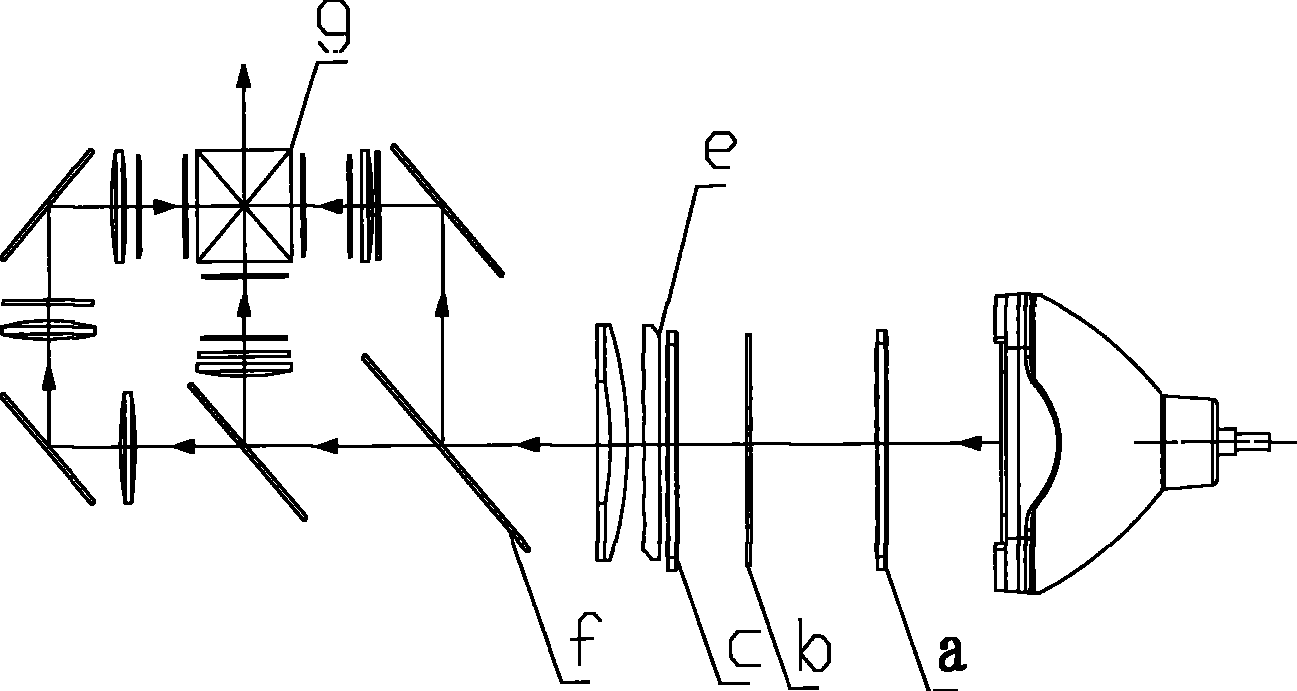
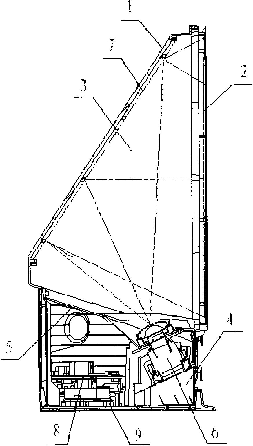
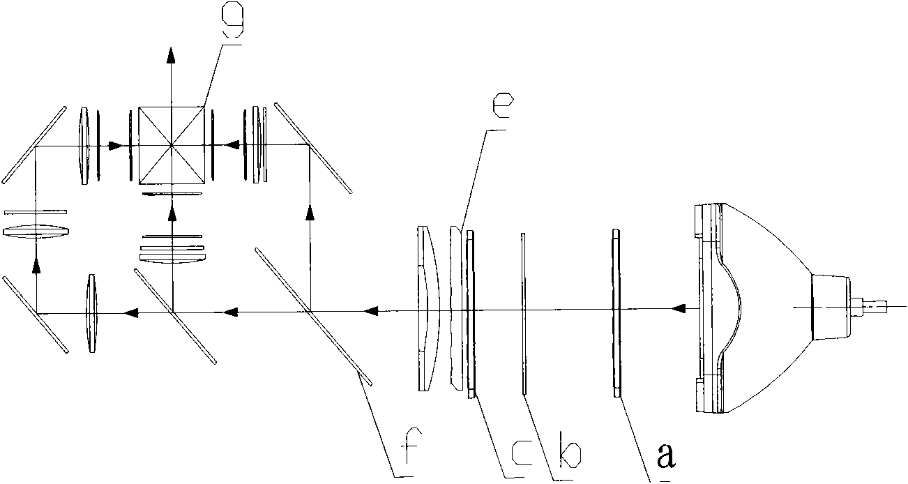
[0016] The high-brightness large-screen TV shown in Figure 1 is composed of a casing 1, a system circuit board 8, an optical projection system, a heat dissipation structure, and a display screen 2. The casing 1 has an upper cavity 3 and a lower cavity 4, and the upper and lower A partition 5 is arranged between the cavities, and the optical projection system includes an optical engine 6 installed on the lower cavity of the casing, a reflector installed in the upper cavity, and a partition between the upper cavity and the lower cavity, reflecting The mirror 7 is installed on the upper cavity, and the system circuit board 8 is arranged on the base plate 9. The optical engine 6 and the system circuit board 8 jointly form a video display system, which is reflected to the display screen 2 by the reflector 7 fixed on the upper cavity. On the screen, enough to become a complete high-brightness large-screen TV. The optical path system of the optical engine as shown in Figure 2 has a l...
PUM
 Abstract
Description
Claims
Application Information