Device for rotating and holding a winding tube and home automation equipment including such device

A technology for home automation and coiling, which can be used in door/window protection devices, windows/doors, building components, etc., and can solve problems such as impossible to adjust coils.

Inactive Publication Date: 2012-02-29
SOMFY SAS
View PDF5 Cites 0 Cited by
  • Summary
  • Abstract
  • Description
  • Claims
  • Application Information

AI Technical Summary

Problems solved by technology

Therefore, it is not possible to adjust the length of the roll tube to fit the width of this screen

Method used


Image

  • Device for rotating and holding a winding tube and home automation equipment including such device
  • Device for rotating and holding a winding tube and home automation equipment including such device
  • Device for rotating and holding a winding tube and home automation equipment including such device

Examples


Embodiment Construction

[0028] The present invention can be used for various types of scrolling screens. The uses described below correspond to one type of screen, the roller blind. Of course, this example is non-limitative and the invention can also be applied to any other type of screen, in particular blinds.

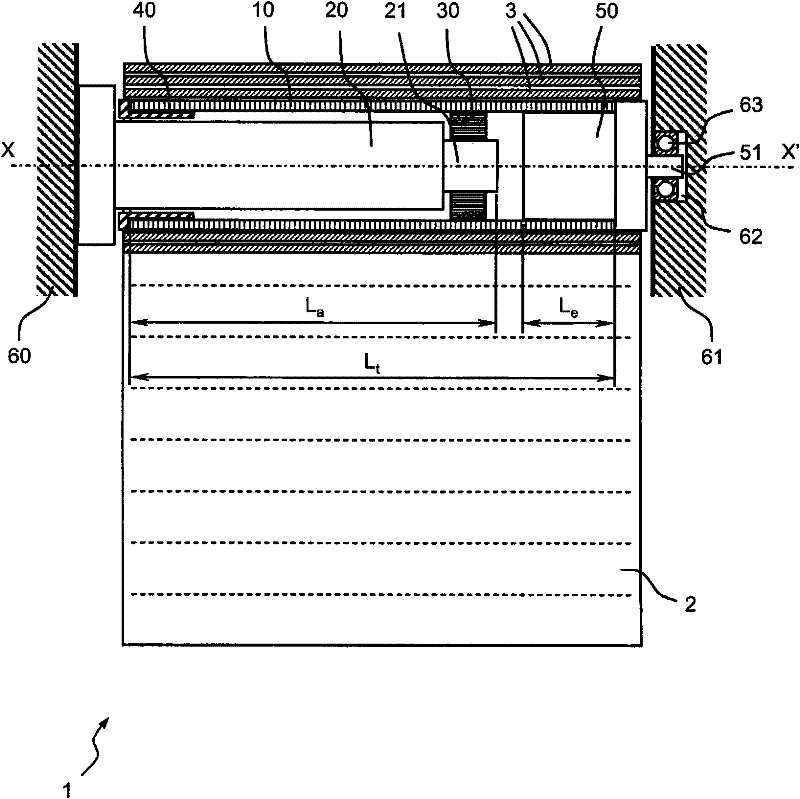
[0029] figure 1 A motor-driven roller blind 1 of known assembly (method) is shown. The slats 3 of the baffle 2 are rolled around the tube 10 . The tube is driven in rotation by a tubular actuator 20 fastened to a frame 60 . A tubular actuator generally comprises a tube into which a gear motor is inserted at one end and a control module inserted into the other end of the tube for controlling the power supply to the gear motor. The gear motor terminates in an output shaft protruding from the tube of the actuator. The output shaft 21 of the actuator transmits the drive torque to a drive wheel 30 fixed to the tube. In order for the tube to rotate about its axis XX', the tube is guided in ...


PUM


Abstract

The invention relates to a device for rotating and holding the winding tube (110) of a mobile screen, that comprises an actuator (120) provided with an output shaft (121) and inserted (F1) into the winding shaft by a first end (111) of said tube (110) and capable of rotating the winding tube (110) via the output shaft (121). The device also includes an end piece (150) defining a holder for the tube (110) equipped with the actuator (120). At least one overlapping portion (153) of the end piece (150) extends axially from the second end (112) of the shaft towards the first end (111) up to at least a portion of the output shaft (121).

Description

technical field [0001] The present invention relates to a device for driving in rotation and supporting a roller tube (upper tube) for moving screens such as slatted or continuous roller blinds or blinds used in home automation equipment. The curtains are rolled up. The invention also relates to a home automation device comprising such a device. Background technique [0002] In order for the screen to be rolled up around the tube, it is necessary to hold the tube in place and guide the tube to rotate about an axis, the roll-up axis. To this end, supports are provided at each end of the tube. When the tube is driven by a motor through a tubular actuator inserted into the tube, the pivotal connection is provided by a ring fixed to the tube and mounted to rotate freely about the tubular body of the actuator, which remains stationary relative to the frame. Usually an embout engages the other end of the tube. The joint cooperates with a support or joue fastened to the frame ...

Claims


Application Information

Patent Timeline
Patent Type & Authority Patents(China)
IPC IPC(8): E06B9/72E06B9/174
CPCE06B9/174E06B9/72
Inventor D·杜麦茨S·安托万
Owner SOMFY SAS
Why Eureka
Try Eureka