
Fault ranging method by utilizing red and green colors to express traveling wave of DC power transmission circuit malfunction voltage

A DC transmission line, fault location technology, applied in the fault location, using the pulse reflection method to detect the fault and other directions, can solve the problems of difficult identification of reflected waves, the second wave head is easily interfered by noise, etc., and achieves intuitive distance measurement. Effect

Inactive Publication Date: 2012-01-11
KUNMING UNIV OF SCI & TECH
View PDF0 Cites 0 Cited by
  • Summary
  • Abstract
  • Description
  • Claims
  • Application Information

AI Technical Summary

Problems solved by technology

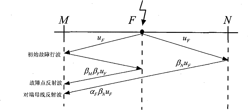
The existing traveling wave single-ended fault location method is basically realized by using wavelet analysis [7] or mathematical morphology [8]. The fault traveling wave is transmitted to the boundary of the DC line, and the reflected wave is in a few microseconds. , the polarity is reversed, which makes identification of the reflected wave difficult; under high-impedance ground faults, the second wave head is susceptible to noise interference

Method used


Image

  • Fault ranging method by utilizing red and green colors to express traveling wave of DC power transmission circuit malfunction voltage
  • Fault ranging method by utilizing red and green colors to express traveling wave of DC power transmission circuit malfunction voltage
  • Fault ranging method by utilizing red and green colors to express traveling wave of DC power transmission circuit malfunction voltage

Examples


Embodiment Construction

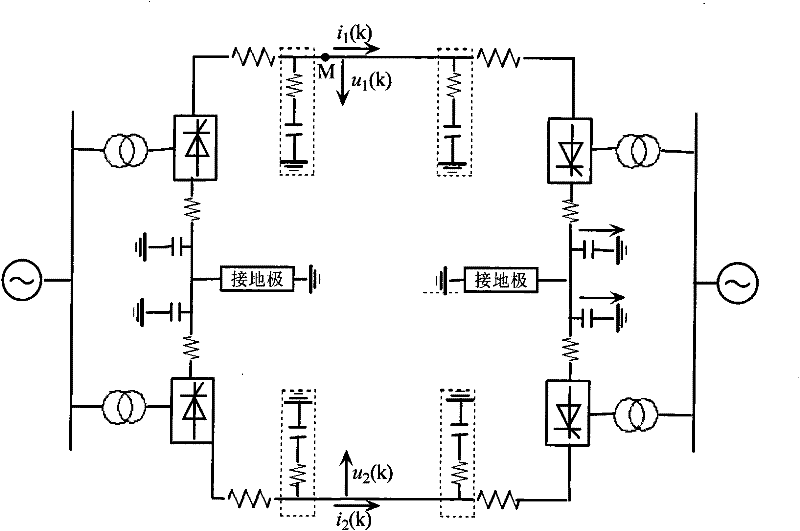
[0037] by image 3 Take the ±500kV bipolar DC system as an example, a positive ground fault occurs at the head end of the DC line with a length of L=500km 150km away from the protection installation, the grounding resistance is 5Ω, and the simulation sampling frequency is 1MHz. The specific implementation steps are as follows:

[0038] 1) When the sudden change in voltage at any pole of the DC line |u(n+1)-u(n)|-|u(n)-u(n-1)| is greater than the set value, where n is the nth sample point, u(n) is the voltage sampling value of the nth sampling point of any one of the two poles, the high-speed data acquisition and wave recording device with a sampling frequency of 1MHz starts, and records the positive and negative voltage traveling waves of the rectifier side 3ms after the fault waveforms, such as Figure 4 shown;

[0039] 2) The rectifier side positive voltage traveling wave u dr1 and negative voltage traveling wave u dr2 press separately

[0040] U ...


PUM


Abstract

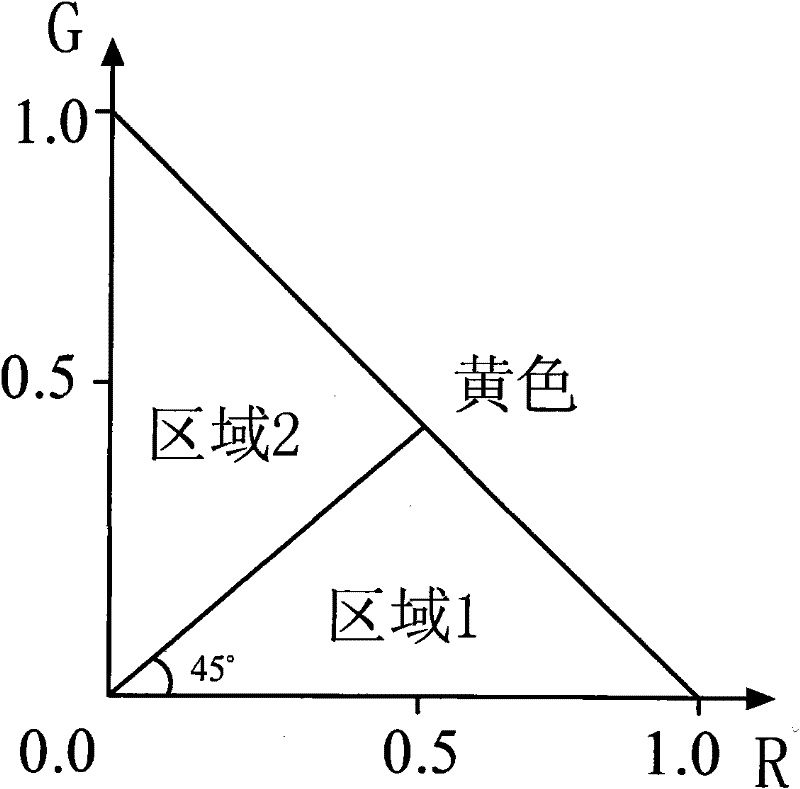
The utility model relates to a fault location method by utilizing red and green colors to express traveling wave of DC power transmission circuit malfunction voltage, which is characterized in that: when the DC power transmission circuit has malfunction, a bipolar voltage traveling wave at a DC circuit protection place at the rectification side is respectively mapped to a red (R) channel and a green (G) channel to form a color mode pattern of the bipolar voltage traveling wave, front two color mutation places in the color mode pattern are selected, and if the mutated colors at the two places are different, the second color mutation corresponds to a fault point reflected wave; and if the mutated colors at the two places are identical, the second mutation corresponds to an opposite-end marginal reflected wave, an image processing software is used for correctly extracting the time corresponding to the mutation, the time is substituted into a single-end location formula to realize the single-end fault location. While the fault location accuracy is ensured, the fault location is more direct.

Description

technical field [0001] The invention relates to a fault ranging method for a DC transmission line fault voltage traveling wave red and green two-color representation, and belongs to the technical field of electric system relay protection. Background technique [0002] Fault location [1-8] has always been highly concerned by electric power workers. Accurate fault location can greatly shorten the line inspection time and speed up the restoration of power supply, which is of great significance to the safe and economical operation of the power system. Traveling wave fault location is a fault location method based on traveling wave transmission theory: when a fault occurs on a transmission line, a fault traveling wave propagating along the line will be generated, and refraction and reflection will occur at the discontinuous point of wave impedance, and the fault traveling wave will be used Transit time calculates distance to fault. The traveling wave method can be divided into s...

Claims


Application Information

Patent Timeline
Patent Type & Authority Patents(China)
IPC IPC(8): G01R31/08G01R31/11
Inventor 束洪春张敏彭仕欣
Owner KUNMING UNIV OF SCI & TECH
Learn More