Ultrasonic flotation method and device and application thereof

A flotation device and ultrasonic technology, used in flotation, solid separation and other directions, can solve the problems of low target ore recovery rate and low concentrate grade, and achieve the effects of saving labor costs, reducing overall energy consumption, and easy automatic control.

Inactive Publication Date: 2010-09-29
佛山市兴民科技有限公司
View PDF12 Cites 26 Cited by
  • Summary
  • Abstract
  • Description
  • Claims
  • Application Information

AI Technical Summary

Problems solved by technology

[0007] There are also some personal patents such as CN200710195594.6, etc., but these patents have not effectively solved the problems of long flotation process time, low target ore recovery rate and low concentrate grade, so it is still necessary to improve

Method used


Image

  • Ultrasonic flotation method and device and application thereof
  • Ultrasonic flotation method and device and application thereof
  • Ultrasonic flotation method and device and application thereof

Examples


Embodiment 1

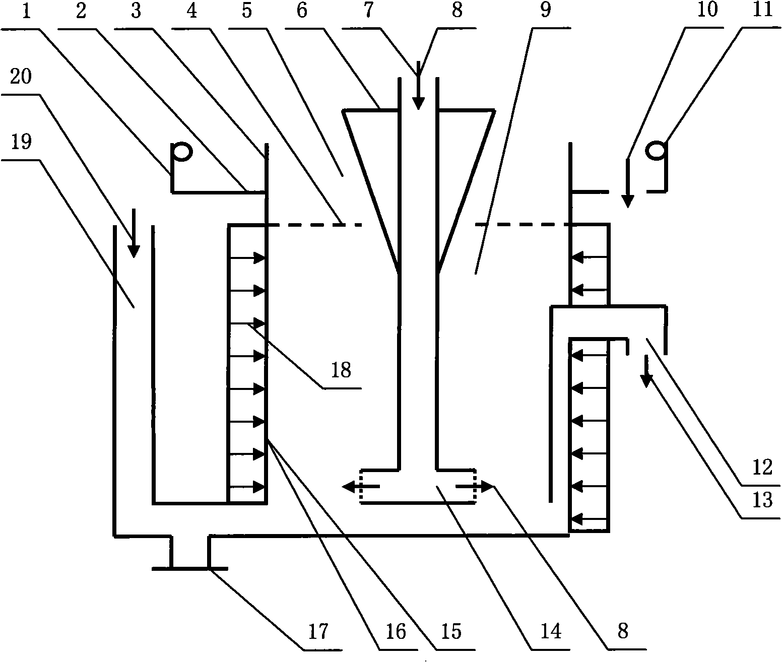
[0038] Example 1: Ultrasonic flotation device that emits ultrasonic waves from the side wall of the flotation tank

[0039] figure 1 It is an ultrasonic flotation device that emits ultrasonic waves from the side wall of the flotation tank. The ultrasonic source frequency of the ultrasonic device 15 is 20kHz, and the sound intensity is 0.5-4w / cm 2 . The ultrasonic emitting surface 16 of the ultrasonic device is submerged and arranged below the liquid surface 4 of the ore slurry. The sound intensity of the ultrasonic source, from the bottom of the flotation tank body 3 to the vertical interval of the slurry liquid level, is set in a way that tends to weaken. That is, the sound intensity of the ultrasonic source at the bottom of the flotation cell is 4w / cm 2 ; When approaching the liquid surface of the slurry, the sound intensity of the ultrasonic source is 0.5w / cm 2 . The ultrasonic source is set in such a way that the sound intensity tends to be weakened, aiming at contro...

Embodiment 2

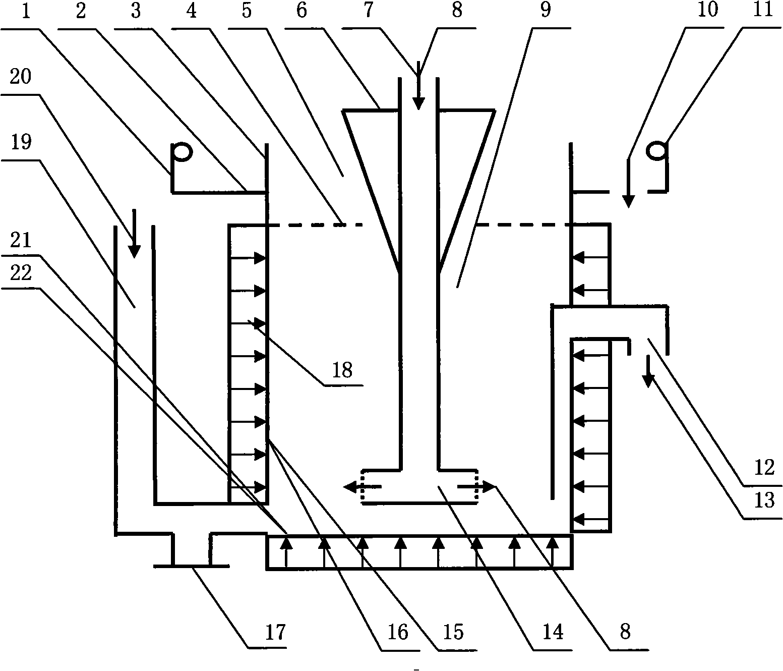
[0042] Embodiment 2: an ultrasonic flotation device that emits ultrasonic waves synchronously from the side wall and bottom of the flotation tank.

[0043] figure 2 It is an ultrasonic flotation device that emits ultrasonic waves synchronously from the side wall and bottom of the flotation tank. The ultrasonic source frequency of the ultrasonic device 15 is 20kHz, and the sound intensity is 2w / cm 2 ; The ultrasonic source frequency of the ultrasonic device 21 is 20kHz, and the sound intensity is 4w / cm 2 . The method of synchronously emitting ultrasonic waves from the side wall and bottom of the flotation tank body 3 aims to increase the intensity of the ultrasonic cavitation effect of ultrasonic energy on the pulp.

[0044] the experiment shows, figure 2 When the ultrasonic flotation device shown is used for flotation of refractory low-grade gold-bearing minerals, the recovery rate of gold-bearing ore is increased by more than 20% compared with conventional flotation dev...

Embodiment 3

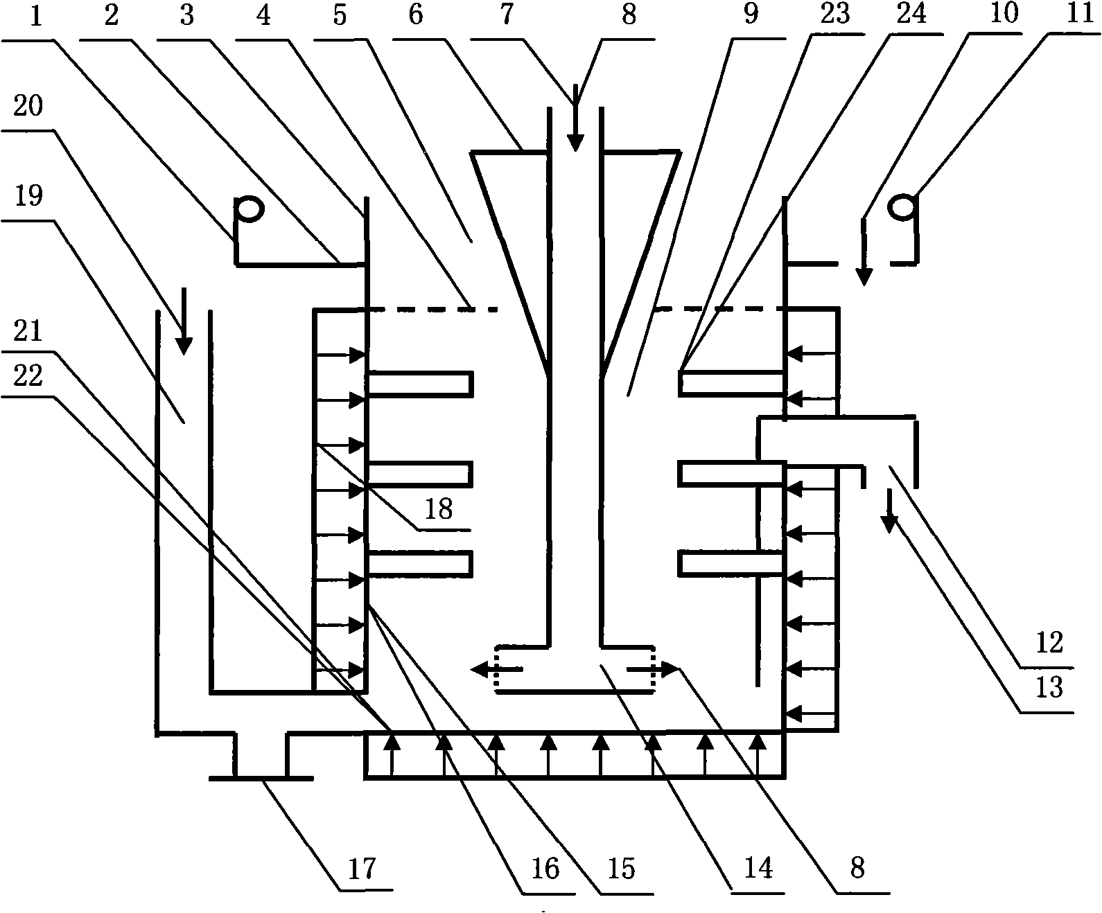
[0046] Embodiment 3: an ultrasonic flotation device that emits ultrasonic waves synchronously from the side wall, bottom and center of the flotation tank.

[0047] image 3 The ultrasonic flotation device shown is in figure 2 More than one ultrasonic device 23 is added in the ultrasonic flotation device shown. The ultrasonic source frequency of the ultrasonic device 23 is 20-128kHz, and the sound intensity is 50-200w / cm 2 ; Its ultrasonic emitting surface 24 adopts a set curved surface to transmit ultrasonic energy to the pulp 9 . This ultrasonic flotation device is mainly used for large-scale flotation production process or ultrasonic flotation of refractory minerals. When the diameter of the ultrasonic flotation device is greater than 2 meters, due to the attenuation and transmission of ultrasonic energy in the pulp, the pulp in the center of the flotation tank is difficult to receive ultrasonic energy from the side wall or bottom of the flotation tank. At this time, se...


PUM


Abstract

The invention relates to an ultrasonic flotation method and a device and application thereof, which comprise the following steps: arranging an ultrasonic device in or outside a floatation tank body, starting the ultrasonic device when the floatation device carries out the mineral floatation, using ultrasonic waves to irradiate floatation pulp, providing a high-energy elastic mechanical wave to the pulp, initiating an ultrasonic cavitation effect, generating a large number of cavitation bubble particle flows which flow at high speed, and effectively washing the surfaces of the ore particles in the pulp to enable target ore particles to expose the fresh surfaces; at the same time, using ultrasonic energy to improve the activity of medicament in the pulp, quickening adsorption process of the medicament and the surfaces of the target ore particles to further improve the effects of breaking, restructuring and floating of mineralized bubbles in a pulp system, and thus realizing the optimization of flotation process.

Description

Technical field [0001] The invention relates to a mineral flotation method and its device and application, in particular to an ultrasonic flotation method and a device for improving the flotation process by using ultrasonic waves, and belongs to the technical field of flotation. Background technique [0002] The flotation process is a wet beneficiation process that uses chemicals to change the surface characteristics of the target ore particles in the pulp, and carries the target ore particles up through the direction of the air bubbles, and is completed in more than one flotation device. It can be seen that the flotation device is the key device of the flotation process. The well-known flotation device usually consists of a flotation cell with a rectangular or circular cross section, a slurry inlet device, a tailings discharge device, a concentrate discharge device, a stirring device, and an air intake device. Under the functional structure of the existing flotation device...

Claims


Application Information

Patent Timeline
Patent Type & Authority Applications(China)
IPC IPC(8): B03D1/02B03D1/14B03B1/00
Inventor 曾兴民梁中堂
Owner 佛山市兴民科技有限公司
Why Eureka
Try Eureka