Eureka AIR delivers breakthrough ideas for toughest innovation challenges, trusted by R&D personnel around the world.

Anti-falling structure for lamp shell

An anti-falling and lamp housing technology, applied in lighting and heating equipment, parts of lighting devices, lighting devices, etc., can solve problems such as increased maintenance cost and maintenance time, easily damaged lamps, hidden safety hazards, etc., and shorten the opening of the cover. Maintenance time, enhance market competitiveness, and save maintenance costs

Inactive Publication Date: 2013-05-08
OCEANS KING LIGHTING SCI&TECH CO LTD +1
View PDF0 Cites 0 Cited by
  • Summary
  • Abstract
  • Description
  • Claims
  • Application Information

AI Technical Summary

Problems solved by technology

[0002] In the field of professional lighting, such as explosion-proof lamps used on oil platforms, due to the particularity of the place of use, the lamps often need to be opened when maintaining other components such as light sources and ballasts. However, often because the lamps are relatively large , during maintenance, in order to ensure its safety and reliability, it is necessary to disassemble the entire lamp for inspection. However, there is no corresponding structural support at present, so it is very difficult to operate, and it is easy to damage the lamp, affecting the normal service life of the lamp. The maintenance will bring a lot of trouble and loss to the user, at the same time, the existing structure also increases the maintenance cost and maintenance time
[0003] Another way is that maintenance personnel climb to a high place to troubleshoot and repair the lamps. Although this method does not need to disassemble the entire lamp, it needs to disassemble the lamp shell first, and then directly perform maintenance on the part. However, when When removing the fasteners connecting the housings one by one, due to the influence of the gravity of the housing itself, careless operation can easily lead to the automatic sliding of the housing, causing safety accidents and potential safety hazards

Method used


Image

  • Anti-falling structure for lamp shell
  • Anti-falling structure for lamp shell
  • Anti-falling structure for lamp shell

Examples


Embodiment Construction

[0020] In order to make the object, technical solution and advantages of the present invention clearer, the present invention will be further described in detail below in conjunction with the accompanying drawings and embodiments. It should be understood that the specific embodiments described here are only used to explain the present invention, not to limit the present invention.

[0021] The invention provides an anti-falling structure for lamps, which is arranged on large-scale explosion-proof lighting lamps in the field, see Figure 4 , Figure 5 , the explosion-proof lamp includes the following components: a housing 4, which contains a hollow cavity for placing the light source drive components, including ballasts and other components; The component is sealed and fixedly connected with the upper end surface of the housing 4 to avoid the intrusion of external impurities such as dust, sand, water, etc.; the lamp ring 5 is sealed and fixedly connected with the lower end sur...


PUM


Abstract

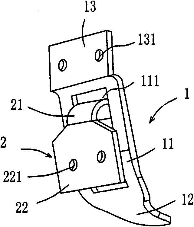
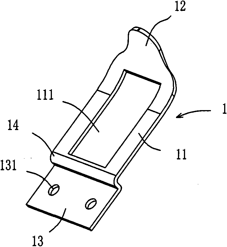
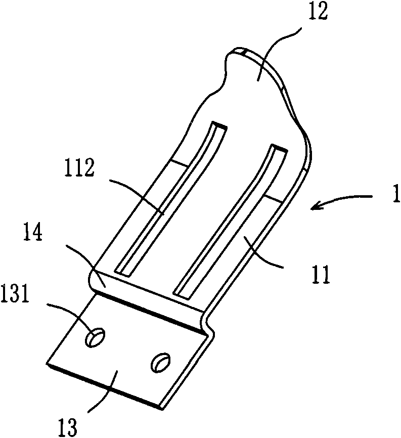
The invention provides an anti-falling structure for a lamp shell, which is arranged in the connection position of a lighting lamp shell and a lamp ring and comprises a movable component and a guide rail component. The movable component comprises a fixed part and a sliding part connected with the upper end of the lamp ring; the sliding part has a hooked or arc structure; the guide rail formed by an integral plate-shaped member component comprises a connecting part and a sliding rail part connected with the bottom of the shell as well as a main body part extending upward along the sliding rail part and for prevention; the connecting part and the sliding rail part are misplaced and the sliding part tilts outward; the sliding rail part is provided with a through hole which is capable of receiving the sliding part and allowing the sliding part to slide therein; and the sliding rail part of the movable component is matched with the sliding rail part of the guide rail component and moves up and down along the sliding rail part. When in use, the anti-falling structure can obviously reduce the time for lamp maintenance with the cover opened, realize rapid maintenance of all the components in the cavity of the lamp, prolong the service life of the lamp, save the maintenance cost, and also enhance the market competitiveness of the lamp, thereby winning the market for the lamp.

Description

technical field [0001] The invention relates to the field of lamps, in particular to an anti-falling-off structure during maintenance of an explosion-proof lamp housing. Background technique [0002] In the field of professional lighting, such as explosion-proof lamps used on oil platforms, due to the particularity of the place of use, the lamps often need to be opened when maintaining other components such as light sources and ballasts. However, often because the lamps are relatively large , during maintenance, in order to ensure its safety and reliability, it is necessary to disassemble the entire lamp for inspection. However, there is no corresponding structural support at present, so it is very difficult to operate, and it is easy to damage the lamp, affecting the normal service life of the lamp. The maintenance will bring a lot of trouble and loss to the user, at the same time, the existing structure also increases the maintenance cost and maintenance time. [0003] An...

Claims


Application Information

Patent Timeline
Patent Type & Authority Patents(China)
IPC IPC(8): F21V17/00
Inventor 周明杰彭云龙
Owner OCEANS KING LIGHTING SCI&TECH CO LTD
Why Eureka
Eureka Blog
Learn More