Aviation moisture separation device

A water-air separation and aviation technology, which is applied in measurement devices, separation methods, dispersed particle separation, etc., can solve the problems of cumbersome maintenance process for cleaning water cups, difficult to ensure the air tightness of products, and complicated gas path transfer structure, etc. Assembly manufacturability, air tightness, and simple structure and installation

Active Publication Date: 2018-07-24
TAIYUAN AERO INSTR
View PDF4 Cites 3 Cited by
  • Summary
  • Abstract
  • Description
  • Claims
  • Application Information

AI Technical Summary

Problems solved by technology

[0003] Existing water-gas separation plant (see figure 1 ) is to lead out the precipitator water cup 12 from the bottom end of the product air source input through the air path adapter frame 11, and the precipitator water cup 12 is installed on the outer surface of the product shell for rainwater and condensed water discharge and removal. This traditional water-gas separation The device gas circuit transfer structure is complicated, and the inner diameter of the pipe leading out of the water cup is required to be not less than Occupies a certain size space inside and outside the product, and the cleaning and maintenance process of the water cup is cumbersome, and the airtightness of the product is not easy to guarantee

Method used


Image

  • Aviation moisture separation device
  • Aviation moisture separation device
  • Aviation moisture separation device

Examples


Embodiment Construction

[0020] Specific embodiments of the present invention will be further described below in conjunction with the accompanying drawings.

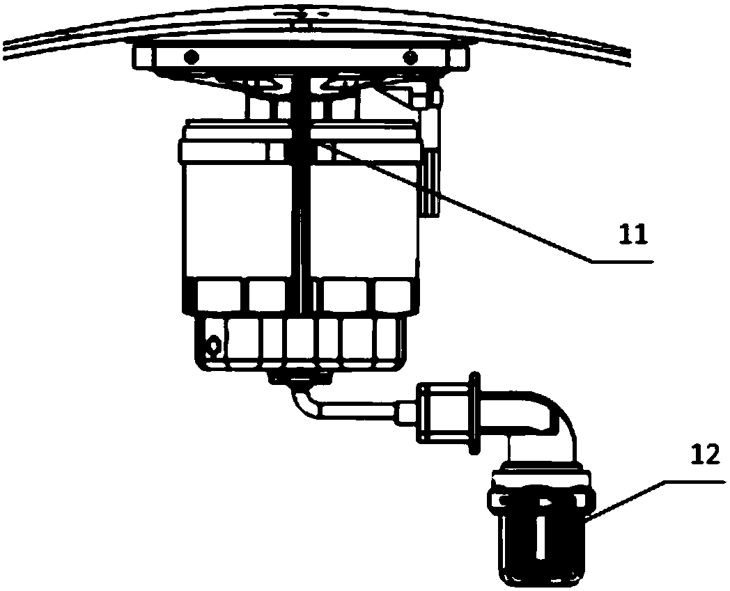
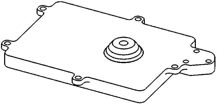
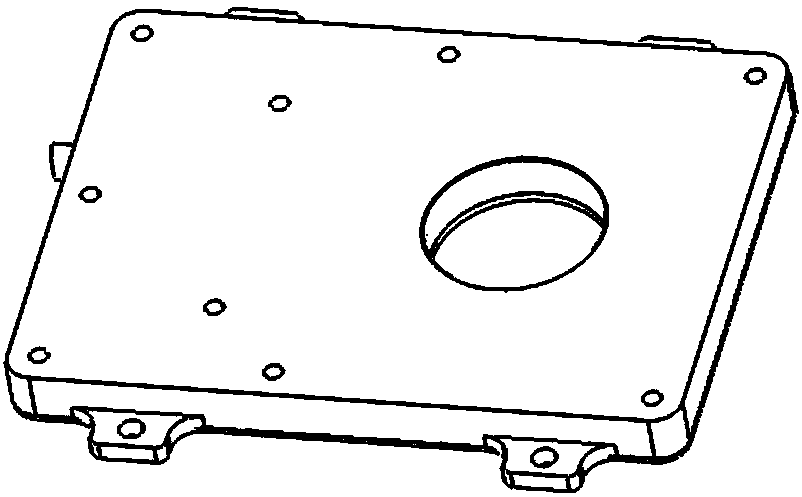
[0021] A kind of aviation water-gas separation device (see Figure 4 , Figure 5 , Figure 6 ), including the dewatering settler chamber 3 (see figure 2 ), water removal heater 2 (see image 3 ); the chamber 3 of the dewatering precipitator is a cavity structure, and the inlet and outlet of the gas source are set; the inlet of the gas source is arranged above the dewatering precipitator chamber 3, and the outlet of the gas source is higher than The bottom surface of the water-removing precipitator chamber 3 ensures that the inlet atmospheric condensed water will sink to the bottom of the chamber and will not enter the pipeline; the inlet of the gas source is communicated with the pressure measuring hole of the body pressure sensor sensing part 1; The outlet of the gas source communicates with the pressure sensor 4 inside the fuselage pressu...


PUM


Abstract

The invention belongs to the technical field of structure design of aviation products, and relates to an aviation moisture separation device. The aviation moisture separation device comprises a dewatering precipitator cavity (3) and a dewatering heater (2); the dewatering precipitator cavity (3) is in a hollow cavity structure and is provided with an inlet and an outlet of an air source; the inletof the air source is arranged at the upper part of the dewatering precipitator cavity (3), and the outlet of the air source is higher than the bottom surface of the dewatering precipitator cavity (3), so that the atmosphere condensate water is guaranteed to sink to the bottom part of the cavity and not to enter a pipeline; the inlet of the air source communicates with a pressure hole of a sensingpiece (1) of an airframe pressure sensor; the outlet of the air source communicates with a pressure sensor (4) in the airframe pressure sensor; the dewatering heater (2) is arranged between the dewatering precipitator cavity (3) and the sensing piece (1) of the airframe pressure sensor, and provides a heat source for the sensing piece (1) of the airframe pressure sensor and the dewatering precipitator cavity (3).

Description

technical field [0001] The invention belongs to the technical field of aviation product structure design and relates to an aviation water-gas separation device. Background technique [0002] The functional structure of the fuselage pressure sensor is composed of surface pressure measurement and atmospheric data calculation. The surface pressure measurement holes are distributed on the curved surface of the fuselage pressure sensor sensing part 1. The layout of the pressure measurement holes is 5-φ2 holes, and the range is In the area of ​​φ10, one of the holes is set at the center of φ10, and the other four holes are symmetrically and evenly distributed around the center hole, and the air paths of 5-φ2 holes are connected to each other. Because the body pressure sensor is exposed to the airflow outside the body, the rain in the atmosphere may enter the product, affecting the pressure transmission accuracy of the product and causing pressure hysteresis. Therefore, the produc...

Claims


Application Information

Patent Timeline
Patent Type & Authority Applications(China)
IPC IPC(8): B01D45/02B01D53/26G01L11/00B01D1/00
CPCB01D1/00B01D45/02B01D53/265G01L11/00
Inventor 聂美英孙肇花
Owner TAIYUAN AERO INSTR
Why Eureka
Try Eureka