Reel seat

A technology of fishing reel seat and fishing reel, which is applied in fishing, application, fishing rod, etc., and can solve the problems of lower quality of fishing reel seat and poor feeling

Active Publication Date: 2010-12-01
SHIMANO INC
7 Cites 3 Cited by

AI-Extracted Technical Summary

Problems solved by technology

[0006] However, in the engagement state of the protrusion and the guide groove, in order to ensure smooth sliding movement of the movable cover, it is necessary to exhibit a loose engagement state, and since the cover main body itself is molded using a molding die products, it ...

Method used

[0064] The parts on both lateral sides of the front side loading surface 2A and the tail side loading surface 2B are not formed as circular arc surfaces, but are formed as an upward inclined surface, that is, the tip side inclined concave surface 2e, Thereby, the outer diameter of the portion corresponding to the two sides can be r...

Abstract

The present invention provides a reel seat, capable of preventing a movable cover from offset so as to improve quality. The movable cover (5) is provided with a leg press body (5B) for pressing and holding a reel leg, a skirt section (5h) is arranged on the leg press body (5B), the skirt section (5h) is clamped and is fixed between a periphery surface of a seat basic section (2) and an inner circumferential surface of a cover main body (5A), the periphery surface of the seat base (2) is provided with an upward rail side sloped recessed surface (2f), and the movable cover (5) is prevented from loosing toward the circumference direction by means of the skirt section (5h) and the rail side sloped recessed surface (2f).

Application Domain

Rods

Technology Topic

EngineeringMechanical engineering

Image

  • Reel seat
  • Reel seat
  • Reel seat

Examples

  • Experimental program(6)

Example

[0042] [First Embodiment]
[0043] The mode of applying the present invention to the fishing rod A will be described below.
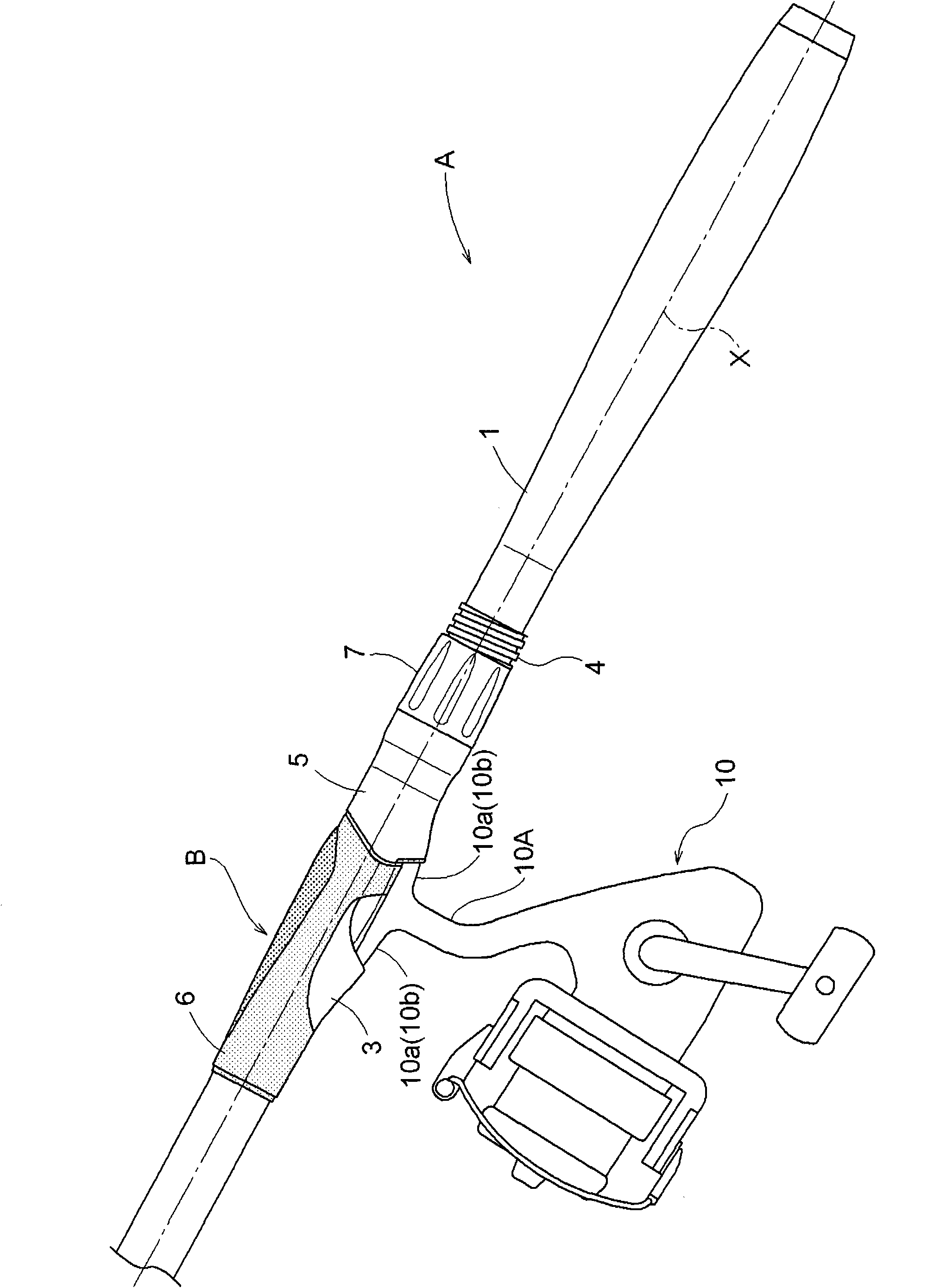
[0044] Such as Figure 1~4 As shown, the fishing rod A is configured such that a cylindrical fishing reel seat B for mounting the reel 10 is mounted on the tail rod 1 as a rod body having a grip portion, and the cylindrical fishing reel seat B is A movable cover 5 is installed on the base 2.
[0045] A fixed cover 3 is integrally formed on the seat base 2. The fixed cover 3 cooperates with the movable cover 5 to face the front leg 10a formed by bending the tip of the fishing reel leg 10A of the reel 10 toward the rod tip side. For holding, on the rear side of the place where the fixed cover 3 is formed, a female screw portion 4 to which the movable cover 5 is screwed is provided.
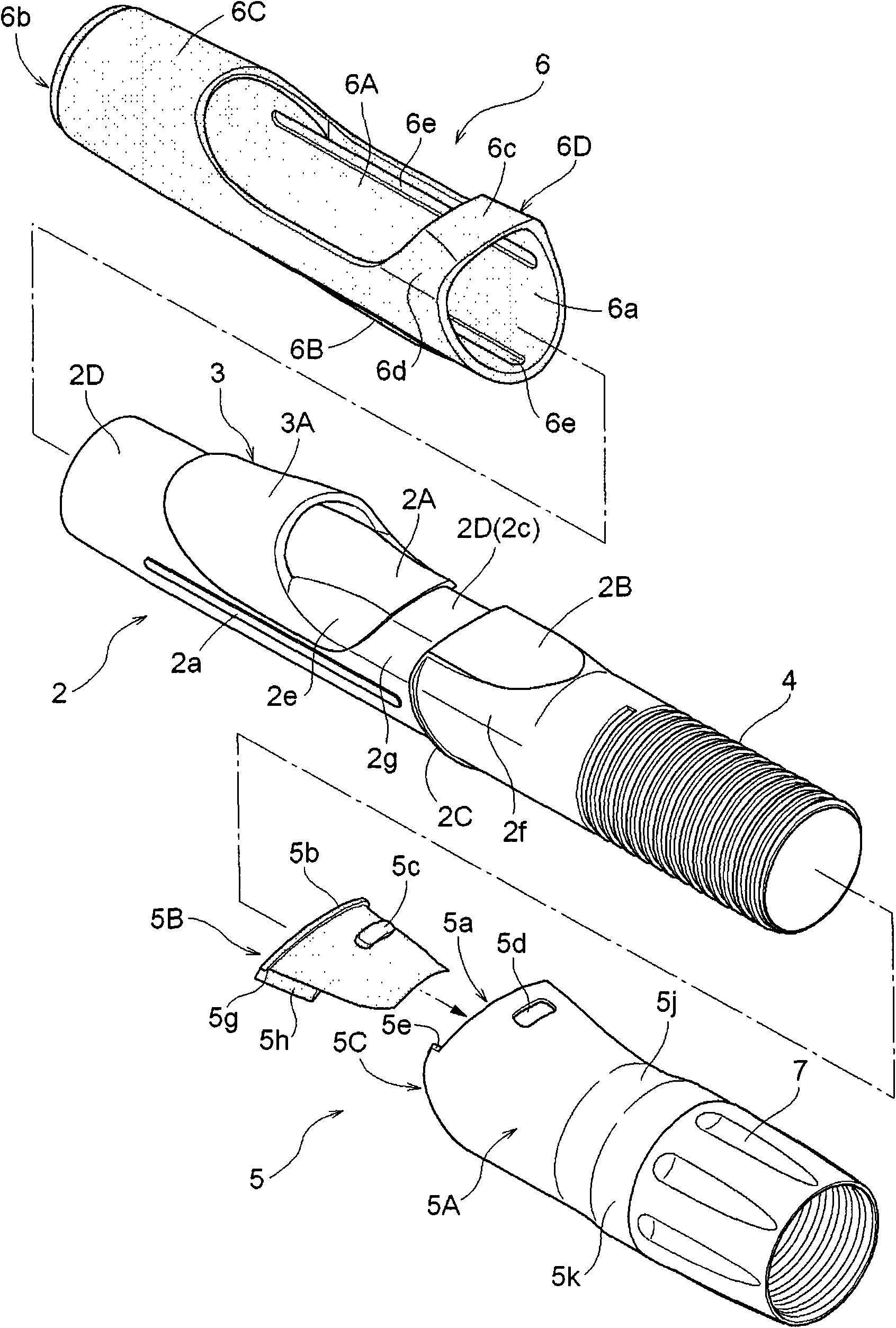
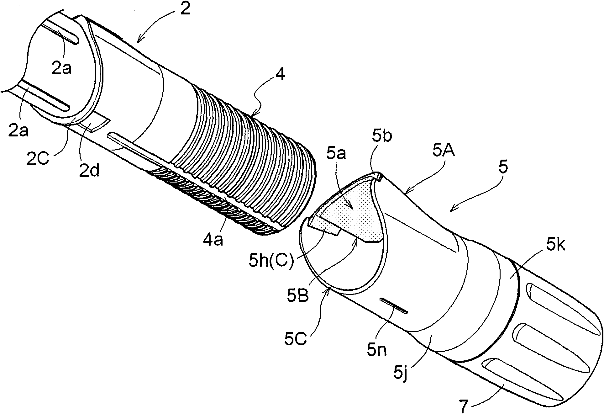
[0046] Such as Figure 4 , Figure 8 with Picture 9 As shown, the movable hood 5 is equipped with a hood body 5A, a leg pressing body 5B, and a nut body 7. The hood body 5A performs an adjustment on the tail side leg 10a formed by bending the tip of the fishing reel leg 10A toward the tail side of the rod. For holding, the leg pressing body 5B is made of resin and is installed in the cover main body 5A, and the nut body 7 makes the cover main body 5A screw and move in the rod axis X direction.
[0047] The seat base 2 will be described.
[0048] Such as Figure 5 As shown, the seat base 2 is a cylindrical body using engineering resins such as polyester, ABS, PET, etc. As described above, the fixed cover 3 protruding outward is formed on the half of the rod tip, and the front mounting surface 2A is formed in the cover of the fixed cover 3 in a submerged state. The front leg portion 10a formed by bending the tip of the fishing reel leg 10A toward the rod tip side is supported by the front mounting surface 2A.
[0049] On the rod tail side of the front mounting surface 2A, an annular flange 2C for positioning is provided, and on the rod tail side of the annular flange 2C, a tail bearing surface 2B that is submerged in the movable cover 5 is formed . The tail-side leg 10a formed by bending the tip of the fishing reel leg 10A toward the tail side of the rod is placed on the tail-side bearing surface 2B.
[0050] Such as figure 2 with Figure 5 As shown, the annular flange 2C slightly extends from the two lateral sides of the rear bearing surface 2B, and surrounds the seat base 2 in a state of recirculating substantially along the circumferential surface of the seat base 2. On the rod tip side of the annular flange 2C, a mounting seat 2D of a rubber grip 6 is formed from the annular flange 2C to the pole tip side. The rubber grip 6 is a grip covering body described later. The mounting seat 2D is formed as a surface that is recessed one step from the annular flange 2C. Such as Figure 4 with Image 6 As shown, when the rubber grip 6 is mounted on the mounting seat 2D, the outer peripheral surface of the rubber grip 6 and the outer peripheral edge of the annular flange 2C are set in the same plane state and formed with a uniform height.
[0051] Such as figure 2 with Figure 5 As shown, the outer surface 3A of the fixed cover 3 is formed in a state protruding one layer from the mounting seat 2D. When the rubber grip 6 is mounted on the mounting seat 2D, the outer surface 3A of the fixed cover 3 is also formed with the rubber The outer surface of the grip 6 is formed in the same plane.
[0052] On the surface of the mounting seat 2D on the side opposite to the existence side of the fixed cover 3 and the surface on the lateral side of the fixed cover 3, there are formed protrusions 2a along the axial direction of the seat base 2. A long groove 6e formed on the inner peripheral surface of the rubber grip 6 on the mounting seat 2D is engaged with a long groove 6e described later, and a structure for suppressing the rubber grip 6 from turning up is adopted.
[0053] A connecting portion 2c as a concave surface is also formed between the front mounting surface 2A and the trailing load surface 2B, and the connecting portion 2c is connected to the other parts of the mounting seat 2D in a state without step. The connecting portion 2c between the side bearing surface 2A and the rear bearing surface 2B also forms a part of the mounting seat 2D. In a state where the rubber grip 6 described later is mounted on the mounting seat 2D, the outer surface of the rubber grip 6 is configured in the same plane as the front mounting surface 2A and the rear mounting surface 2B.
[0054] The part of the seat base 2 that supports the front leg 10a and the tail leg 10a of the fishing reel leg 10A will be described in detail. Such as figure 2 , Figure 4 ~ Figure 8 As shown, the cross-sectional shape of the front mounting surface 2A is the shape of an arc as described above. Image 6 In the plan view shown, the horizontal width in the left-right direction gradually decreases toward the tail side of the rod.
[0055] On the other hand, the trailing side bearing surface 2B has a substantially constant wide lateral width, and the end of the rod trailing side has a shape in which the lateral width in the left-right direction is reduced. Such as Image 6 As shown, the connecting portion 2c that forms a part of the mounting seat 2D of the rubber grip 6 between the front mounting surface 2A and the rear load surface 2B has a width corresponding to the rod end of the front mounting surface 2A. L1 and the lateral width L2 of the pole tip side end of the tail bearing surface 2B are continuously connected.
[0056] On both lateral sides of the front mounting surface 2A, left and right disc-shaped tip-side inclined concave surfaces 2e are formed, and the left and right disc-shaped tip-side inclined concave surfaces 2e are slightly concave in the direction of the rod axis It is formed in an upwardly inclined state with a narrower left-right interval as the end of the tip-side inclined concave surface 2e on the left and right is closer to the front mounting surface 2A. On both lateral sides of the trailing side bearing surface 2B, similarly formed upwardly inclined concave surfaces 2f of the trailing side, and in the mounting seat 2D, the peripheral surface part except the connecting portion 2c is formed to constitute the mounting seat 2D Part of the arc-shaped surface 2g. Since the arc-shaped surface 2g is a part of the mounting seat 2D, it is related to the obliquely upwardly inclined concave surface 2e on the pole tip side and the obliquely upwardly inclined rearwardly inclined concave surface on the pole end. Compared with 2f, it is formed only by a depth equivalent to the thickness of the rubber grip 6.
[0057] The rubber grip 6 is explained below. Such as figure 2 , Figure 4 ~ Figure 8 As shown, the rubber grip 6 is a cylindrical body made of rubber such as NBR, and the fixed cover 3 protrudes from the rubber grip 6 in the state of being installed on the mounting seat 2D, forming an elliptical penetration 孔6A.
[0058] The portion 6C of the rubber grip 6 located on the rod tip side of the through hole 6A is formed in a gentle conical cylindrical shape with a smaller diameter as the opening 6b on the rod tip side approaches. On the other hand, on the rod tail side of the rubber grip 6 is also formed a cylindrical rod tail side part 6D, and on the rod tail side part 6D is formed a circular arc on the rod tail side of the rubber grip 6 The bearing surface portion 6c, and the left and right disc-shaped middle inclined concave surface portion 6d, the middle inclined concave surface portion 6d is recessed in the direction of the rod axis on both lateral sides of the bearing surface portion 6c, and is more The end portion located on the side of the load-bearing surface portion 6c is in an upwardly inclined state with the mutual left-right space narrowed.
[0059] Through the middle inclined concave surface 6d, when the rubber grip 6 is installed at a predetermined position, the inclined upward inclined concave surface 2e formed on the seat base 2 and the inclined upward inclined surface 6d of the rubber grip 6 Can be connected without stratification.
[0060] Such as Figure 5 ~ Figure 8 As shown, on the side 180° opposite to the existence side of the through hole 6A, there is provided a bulging part 6B that bulges slightly to the outside compared to the other parts, in order to make it difficult for the fingers held on the bulging part 6B to slide , And it has been surface processed. That is, in order to suppress surface slippage, pear ground processing to form fine irregularities was performed.
[0061] On the inner peripheral surface of the bulging portion 6B, on the side 180° opposite to the existence side of the through hole 6A, and on three locations on the left and right side surfaces, narrow long grooves 6e are formed along the rod axis X direction. , When the rubber grip 6 is installed on the seat base 2, the narrow long groove 6e is externally fitted and engaged on the protrusion 2a protrudingly formed on the seat base 2 to position the rubber grip 6, and The structure that prevents the rubber grip 6 from turning up.
[0062] Such as Figure 4 As shown, when the rubber grip 6 constructed as described above is externally fitted to the mounting seat 2D from the rod tail side opening 6a, the outer surface of the rubber grip 6 and the outer surface 3A of the fixed cover 3 are in the same plane state. The outer edge surrounding the pole tail side opening 6a abuts on the annular flange 2C, and the outer surface of the rubber grip 6 and the outer surface of the annular flange 2C are connected in the same plane state.
[0063] Such as Figure 4 with Image 6 As shown, in the state where the rubber grip 6 is mounted on the mounting seat 2D, the front side mounting surface 2A, the rear side load surface 2B, and the load surface 6c of the rubber grip 6 are formed in the direction along the rod axis X The upper continuous foot bearing surface. Such as Image 6 As shown in (a), the lateral width of the foot bearing surface is formed so that the lateral width becomes smaller and narrower toward the part located in the middle along the rod axis X direction.
[0064] The parts located on both lateral sides of the front mounting surface 2A and the trailing load surface 2B are not formed as circular arc surfaces, but are formed as upwardly inclined surfaces, that is, the tip-side inclined concave surface 2e. Therefore, The outer diameter of the part corresponding to the two sides can be reduced, and since the part located in the middle along the rod axis X direction, the width becomes smaller and narrower. When the front foot 10a and the tail foot 10a of the reel leg 10A are held together with the seat base 2, they can be easily held.
[0065] And, as described later, when the rubber grip 6 is attached to the arc-shaped surface 2g, the middle inclined concave surface 6d formed on the rubber grip 6 becomes the tip side that is located on the side of the rod tip and is inclined upward. The inclined concave surface 2e is in a continuous state without step difference, so it is not easy to press the fingers and palms, and the hand does not feel pain and the burden is small when the hook is thrown in and the fish is caught.
[0066] The movable cover 5 will be described. Such as Figure 2~Figure 9 As shown, the movable cover 5 is equipped with a cover body 5A made of light metal such as aluminum or titanium, and a rubber or synthetic resin leg pressing body built into the fishing reel leg insertion holder 5a of the cover body 5A 5B.
[0067] The leg pressing body 5B is formed into a substantially arc shape with a fishing reel leg insertion holding portion 5a built therein, a flange portion 5b protruding from the pole tip side end of the cover body 5A, and protrusions 5c are provided at the left and right center portions, The protrusion 5c is fitted into the through hole 5d formed in the top wall portion of the cover main body 5A, so that the leg pressing body 5B can be positioned.
[0068] Such as Picture 9 As shown, the cross-sectional shape of the cover main body 5A is formed by integrally forming a roughly three-quarter arc-shaped part of the seat base 2 and an arched fishing reel leg insertion holding part 5a. Long elliptical shape and integrally formed by a forming die.
[0069] As described above, the cover main body 5A is integrally formed by a molding die. Therefore, it has not shown high formability to the extent that it can be in close contact with the outer peripheral surface of the seat base 2 in the past. Therefore, when the cover main body 5A is installed in a predetermined position Under the condition, looseness will inevitably occur in the circumferential direction.
[0070] Therefore, the offset suppression mechanism C is provided to suppress this looseness. Here, first, the attachment structure of the cover main body 5A and the leg pressing body 5B will be described, and then the offset suppression mechanism C will be described.
[0071] That is, as Picture 9 As shown, an upward stepped portion 5e is provided in the vicinity of the connection portion between the approximately three-quarter arc-shaped portion of the cover main body 5A and the arched fishing reel leg insertion holding portion 5a.
[0072] On the other hand, in the leg pressing body 5B, 5 g of downward steps are formed on the outer surface in the vicinity of both lower ends on the left and right. When the leg pressing body 5B is inserted into the fishing reel leg insertion holding portion 5a of the cover body 5A, the downward step 5g of the leg pressing body 5B abuts the upward step 5e of the cover body 5A from above, thereby Install the support leg pressing body 5B.
[0073] At the lower ends of the left and right sides of the leg pressing body 5B, a thin skirt 5h extends downward, and the skirt 5h adopts a structure in which the thickness gradually decreases downward. On the other hand, on the outer surface of the seat base portion 2 corresponding to the skirt portion 5h, as described above, a disc-shaped tail-side inclined concave surface 2f that is concavely inclined upward is formed. Furthermore, the skirt portion 5h is in contact with the rear side inclined concave surface 2f and is stopped, whereby the lower end portion of the skirt portion 5h is clamped and fixed by the outer peripheral surface of the cover main body 5A and the seat base 2.
[0074] Here, the skirt part 5h is called a contact part. The rear inclined concave surface 2f is called a receiving portion. Such a skirt portion (abutting portion) 5h and a rear inclined concave surface (receiving portion) 2f constitute a deviation suppression mechanism C.
[0075] With such a structure, even if the movable cover 5 tends to rotate in the circumferential direction together with the leg pressing body 5B, the lower end of the skirt portion 5h is sandwiched and fixed by the outer peripheral surface of the cover body 5A and the seat base 2, thereby suppressing rotation. Therefore, the looseness in the circumferential direction of the movable cover 5 can be suppressed, and the fingers holding the cylindrical fishing reel seat B can be stabilized.
[0076] In this way, the skirt portion 5h is formed only on the leg pressing body 5B made of resin or rubber without passing through the cover main body 5A made of metal, so that the offset suppression mechanism C is formed. Therefore, the offset suppression mechanism C can be configured to be assured by the elastic deformation force of the resin or rubber of the leg pressing body 5B even when the outer peripheral surfaces of the cover body 5A and the seat base 2 are formed with a slight individual error. The state in which the lower end portion of the fixed skirt portion 5h is sandwiched by the outer peripheral surface of the cover main body 5A and the seat base portion 2 is maintained, thereby exhibiting a good offset suppression function.
[0077] Such as Figure 2 ~ Figure 6 As shown, the cover main body 5A of the movable cover 5 is formed with a middle reduced diameter part 5j whose outer diameter is reduced from the fishing reel leg insertion holding part 5a holding the fishing reel leg 10A to the rod tail side, and is reduced in the middle. A stop part 5k having a larger diameter than the outer diameter of the intermediate diameter-reduced part 5j is formed on the rod tail side of the diameter part 5j.
[0078] With the above structure, when the fishing reel leg 10A and the cylindrical fishing reel seat B are held together for fishing, the palm of the hand rests on the bulging portion 6B of the rubber grip 6 to become the tip of the rod. In a state where the movement of the side is suppressed, the little finger rests on the middle reduced-diameter portion 5j of the movable cover 5, and its movement to the rod tail side is suppressed by the stopper 5k, thereby achieving a stable holding state.
[0079] Such as Figure 2 ~ Figure 6 As shown, the annular flange 2C that stops the rubber grip 6 surrounds the entire circumferential surface except for the rear bearing surface 2B, and tends to be 180° opposite to the rear bearing surface 2B. It is formed in a way that one side, more and more to the tail side of the rod. According to this structure, the end of the rod end of the rubber grip 6 positioned in contact with the annular flange 2C protrudes toward the end of the rod on the side 180° opposite to the side where the tail bearing surface 2B exists. Positioning. That is, as Figure 5 with Image 6 As shown, compared with the imaginary reference line Y on the rod tip end side of the annular flange 2C, the rod tail side end of the rubber grip 6 protrudes toward the rod tail side.
[0080] Moreover, in the movable cover 5, as Figure 5 with Figure 7 As shown, the side view shape of the opening edge of the rod tip side end 5C of the cover main body 5A is formed to form the upper half 5f of the fishing reel leg insertion holder 5a and the lower half 5p that is externally fitted on the seat base 2. The part corresponding to the middle position of the rod protrudes most to the tip side of the rod. In the lower half 5p, along the annular flange 2C, toward the side 180° opposite to the existence side of the fishing reel leg insertion holding portion 5a, the opening edge of the rod tip side end 5C of the cover body 5A The side-view shape is formed in a state where it is shifted toward the tail side of the rod.
[0081] Therefore, both the annular flange 2C and the movable cover 5 are in a shape that is offset to the tail side of the rod on the surface opposite to the side where the fishing reel leg is placed at 180°. Therefore, on the reference line Y On the pole tail side, the rubber grip 6 is in a state of protruding and exposed to the pole tail side.
[0082] With such a structure, the thumb part of the fingers holding the fishing reel leg 10A and the seat base 2 is in contact with the rubber grip 6, and it is not easy to feel the pressure.
[0083] In addition, such as figure 1 with Figure 4 As shown, the movable cover 5 abuts on the annular flange 2C, and thereby, the movement to the side where the fixed cover 3 exists can be restricted. That is, the left and right ends of the leg pressing body 5B attached to the fishing reel leg insertion holding portion 5a of the movable cover 5 abut the upper end of the annular flange 2C, and the tip of the cover body 5A The side end 5C also abuts on the annular flange 2C, and therefore can restrict movement to the fixed cover 3 side.
[0084] With such a structure, the outer peripheral surface of the movable cover 5, the annular flange 2C, and the outer peripheral surface of the rubber grip 6 are connected in a substantially same plane state, and it is difficult to give a feeling of pressure to the hand holding this part.
[0085] Such as image 3 , Figure 7 ~ Figure 9 As shown, on the side of the movable cover 5 opposite to the fishing reel leg insertion holding portion 5a at 180°, an inwardly protruding engagement protrusion 5n is provided, and the engagement protrusion 5n is connected to the seat base 2 The guide groove 4a formed on the female threaded portion 4 on the end of the rod engages, so that the movable cover 5 can be slidably moved in the axial direction of the seat base 2 by the rotation of the nut body 7.
[0086] Such as image 3 , Figure 5 with Figure 7 As shown, the seat base 2 is formed on the opposite side of the seat base 2 from the rear side bearing surface 2B with the rod axis X interposed therebetween, and a recessed portion 2d recessed toward the rod axis X is formed.
[0087] The recessed portion 2d is formed recessed between the rod tip end of the guide groove 4a and the annular flange 2C, and its width in the circumferential direction is within a range of approximately 30°. In addition, as the recessed portion 2d, within a range to avoid interference with the movable cover 5, a range of 30° to 90° may be adopted for the width in the circumferential direction.
[0088] The reason for providing such a recessed part 2d is as follows.
[0089] That is, when the movable cover 5 is moved together with the nut body 7 in order to hold the fishing reel leg 10A, the leg pressing body 5B becomes the outer shell part that straddles the tail side leg 10a formed on the fishing reel leg 10A Because of the state on the upper inclined surface 10b, the movable cover 5 is pushed up by the tail-side leg portion 10a of the fishing reel leg 10A, and is eccentric with respect to the seat base portion 2.
[0090] In this way, in the opening edge of the cover main body 5A of the movable cover 5 toward the fixed cover 3 side, the end edge on the side opposite to the fishing reel leg insertion holding portion 5a is in a state of biting into the outer peripheral surface of the seat base 2.
[0091] Generally, on the surface of the seat base 2, suitable paints such as polyurethane resin paints and epoxy resin paints are selected and painted by cloth brushing and spraying.
[0092] However, in this way, when the end edge on the opposite side is in a state of biting into the outer peripheral surface of the seat base 2, defects such as peeling of the painted surface may occur.
[0093] Therefore, by forming the recessed portion 2d as described above, it is possible to prevent the opposite end edge of the movable cover 5 from biting into the outer peripheral surface of the seat base 2, and it is possible to suppress defects such as paint peeling.
[0094] [Other embodiments of the first embodiment]
[0095] (1) In the above, the offset suppression mechanism C is provided on the skirt portion 5h of the leg pressing body 5B, but instead of the foot pressing portion 5B, a portion corresponding to the skirt portion 5h may be formed on the cover main body 5A.
[0096] (2) The above structure is a structure that guides the sliding movement of the movable cover 5 in the rod axis X direction, and the relationship between the guide groove 4a and the engagement protrusion 5n is higher than the conventional structure, but in order to suppress the movement The displacement (slack) of the cover 5 in the circumferential direction may be configured by using the guide groove 4a and the engagement protrusion 5n also as the displacement suppression mechanism C.

Example

[0097] [Second Embodiment]
[0098] In the first embodiment, the embodiment in which the annular flange 2C is not formed on the seat base 2 is regarded as the second embodiment. Therefore, the portion where there is no annular flange 2C and the other outer peripheral surface of the seat base 2 are in the same plane.

Example

[0099] [Third Embodiment]
[0100] In the first embodiment, the embodiment in which the rubber grip 6 is not mounted on the seat base 2 is regarded as the third embodiment. Therefore, there is no mounting seat 2D for attaching the rubber grip 6 formed on the seat base 2, and the outer surface of the seat base 2 is formed in the same plane as the outer surface of the fixed cover 3.

PUM

no PUM

Description & Claims & Application Information

We can also present the details of the Description, Claims and Application information to help users get a comprehensive understanding of the technical details of the patent, such as background art, summary of invention, brief description of drawings, description of embodiments, and other original content. On the other hand, users can also determine the specific scope of protection of the technology through the list of claims; as well as understand the changes in the life cycle of the technology with the presentation of the patent timeline. Login to view more.
Why Eureka
Try Eureka