

Ship
A ship-borne and rotor technology, applied in the field of ships, can solve problems such as uneven distribution of total fluid
- Summary
- Abstract
- Description
- Claims
- Application Information
AI Technical Summary
Problems solved by technology
Method used
Image

Examples
Embodiment Construction
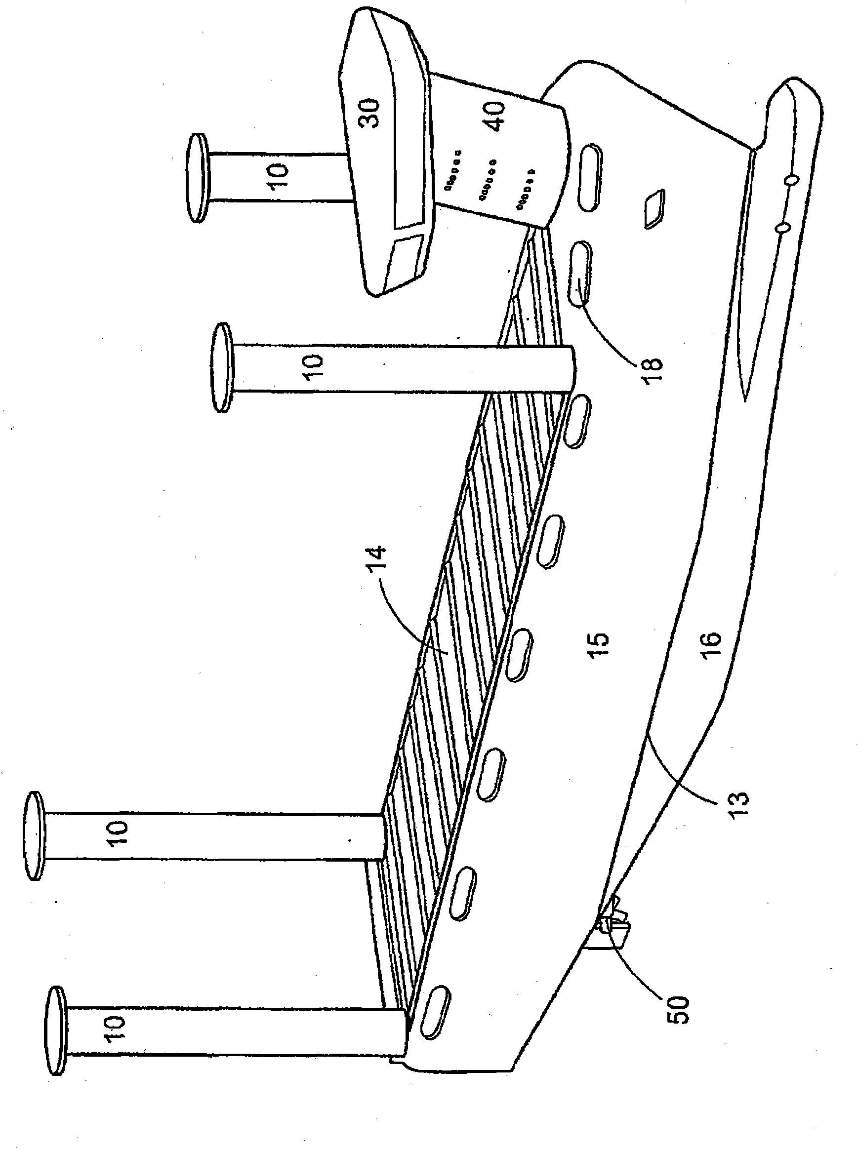
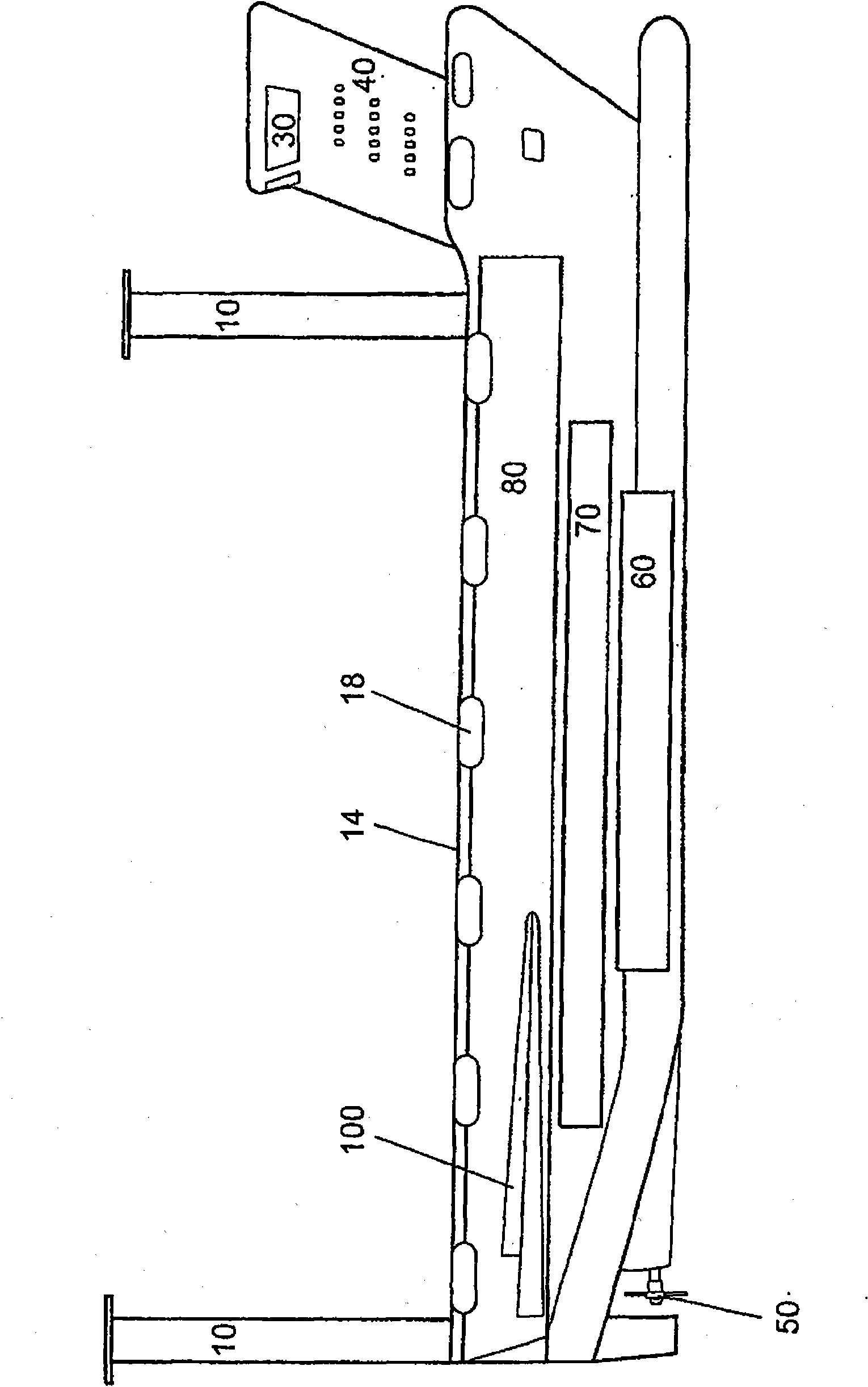
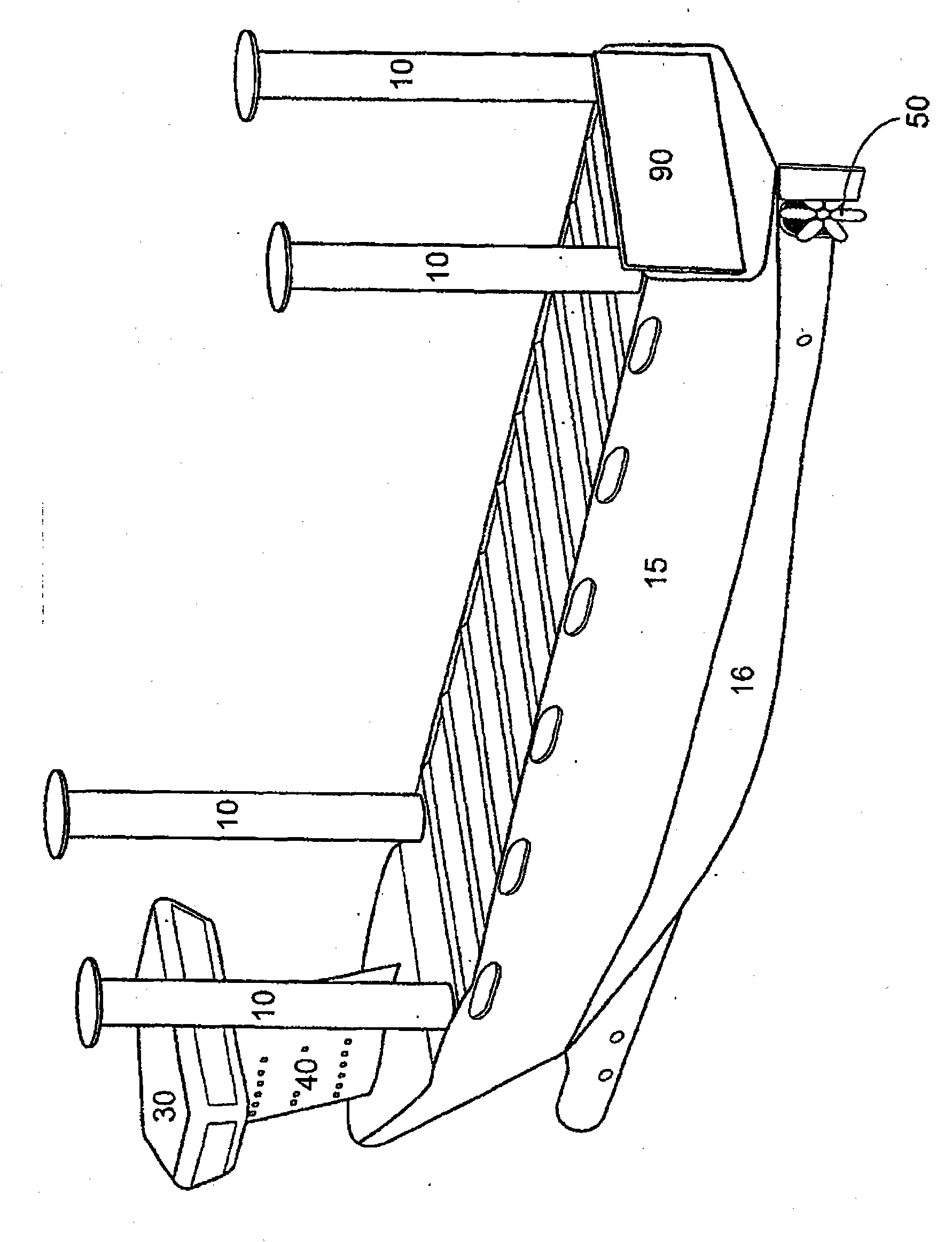
[0027] figure 1 A schematic diagram of a ship according to a first embodiment is shown. In this example, the boat has a hull comprising a submerged part 16 and a submerged part 15 . The boat further has Magnus rotors or Flettner rotors 10 arranged at the four corners of the hull. The ship has a deckhouse 40 with a bridge 30 arranged on the foredeck. The boat has a propeller 50 located underwater. To improve maneuverability, the boat can also have transverse propulsion rudders, wherein preferably one propulsion rudder is arranged at the stern and one or two propulsion rudders are arranged at the bow. Preferably, the above-mentioned lateral propulsion rudder is electrically driven. The berths, kitchen, warehouse, canteen, etc. are arranged in the deckhouse 40 . In this example, the deckhouse 40, the bridge 30 and all superstructures located above the weather deck 14 have an aerodynamic profile that reduces wind resistance. In particular, this is achieved by substantially a...
PUM
 Abstract
Description
Claims
Application Information