Optical-electronic distance measuring device

A technology of photoelectric distance measurement and equipment, which is applied in the direction of radio wave measurement system, measurement device, electromagnetic wave reradiation, etc., and can solve the problems of long effective burst time and unfavorable filter

Inactive Publication Date: 2011-01-12
LEICA GEOSYSTEMS AG
View PDF3 Cites 10 Cited by
  • Summary
  • Abstract
  • Description
  • Claims
  • Application Information

AI Technical Summary

Problems solved by technology

[0016] However, the relatively long period required for filter synchronization proves to be disadvantageous because, contrary to the practical idea of ​​the burst modulation principle, a relatively long effective burst time must also be chosen

Method used


Image

  • Optical-electronic distance measuring device
  • Optical-electronic distance measuring device
  • Optical-electronic distance measuring device

Examples


Embodiment Construction

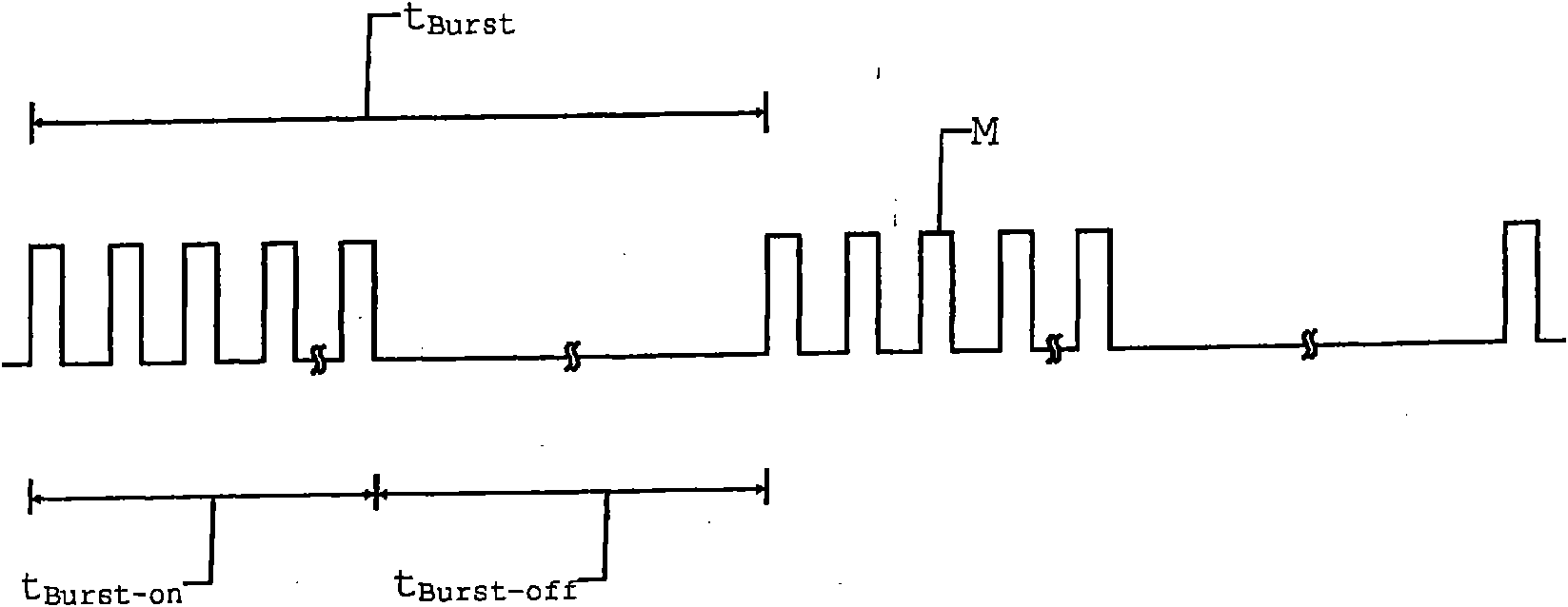
[0040] figure 1 A burst modulation signal diagram is shown to illustrate the characteristics of burst modulation of emitted optical radiation. The duration during which a modulating signal M with a specific modulating frequency exists is called the effective burst time t Burst-on . On the other hand, the dead time t Burst-off is the duration of the absence of the modulating signal M. Effective burst time t Burst-on and dead time t Burst-off constitutes a period known as the burst period t Burst , where t Burst = t Burst-on +t Burst-off .

[0041] The duty cycle of a burst signal is defined as the effective burst duration t Burst-on with measuring cycle t Burst percentage. Consequently, pulse train modulation differs from pulse modulation in that the modulating signal is present quasi-continuously over the entire duration of the measurement period. In the case of burst modulation, on the other hand, only during the burst period t Burst Modulating signal M exists o...


PUM


Abstract

The invention relates to an optical-electronic distance measuring method according to the phase measurement principle by emitting of optical measuring radiation, which is modulated according to the burst modulation principle, having a burst period duration made of an active burst time and a dead time, receiving at least a part of the measuring radiation (23), which is reflected on the measured object, wherein transforming into an input measuring signal (ES) is performed, and determining a distance to the measured object by analyzing a measuring signal (MS, gMS) generated from the input measuring signal (ES).

Description

technical field [0001] The invention relates to an optoelectronic distance measuring method according to the preamble of claim 1 , an optoelectronic distance measuring device according to the preamble of claim 17 , and a receiving circuit for optoelectronic distance measuring according to the preamble of claim 11 . Background technique [0002] Common types of electro-optical distance measuring devices are well known from the prior art. They have a range of tens of meters and are often handheld. They are mainly used for architectural surveying or interior finishing, for example, for 3D measurements of houses. Other fields of use of distance measuring devices are geodetic and industrial surveying. The basic principle of distance measurement with known distance-measuring devices is based on the evaluation of the temporal variation of the properties of the electromagnetic radiation emitted by the distance-measuring device and reflected by the targeted object. For this purpos...

Claims


Application Information

Patent Timeline
IPC IPC(8): G01S17/10G01S17/36G01S7/484G01S7/491G01S7/4912
CPCG01S7/4912G01S17/36G01S7/491G01S7/484G01S17/10
Inventor 彼得·弗勒库尔特·吉热
Owner LEICA GEOSYSTEMS AG
Why Eureka
Try Eureka