
Spark free improved connector

A connector, spark-free technology, applied in the direction of connections, parts of connecting devices, electrical components, etc., can solve problems such as arc discharge

Active Publication Date: 2011-02-02
奥斯卡·汉斯·沃尔夫冈·克斯特尔
View PDF5 Cites 0 Cited by
  • Summary
  • Abstract
  • Description
  • Claims
  • Application Information

AI Technical Summary

Problems solved by technology

However, even with small currents used for communication signals, there is always a risk of arcing, which is undesirable in environments with flammable atmospheres

Method used


Image

  • Spark free improved connector
  • Spark free improved connector
  • Spark free improved connector

Examples


Embodiment Construction

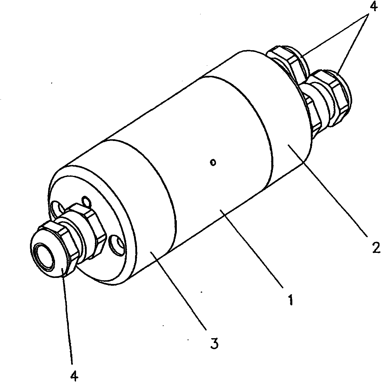
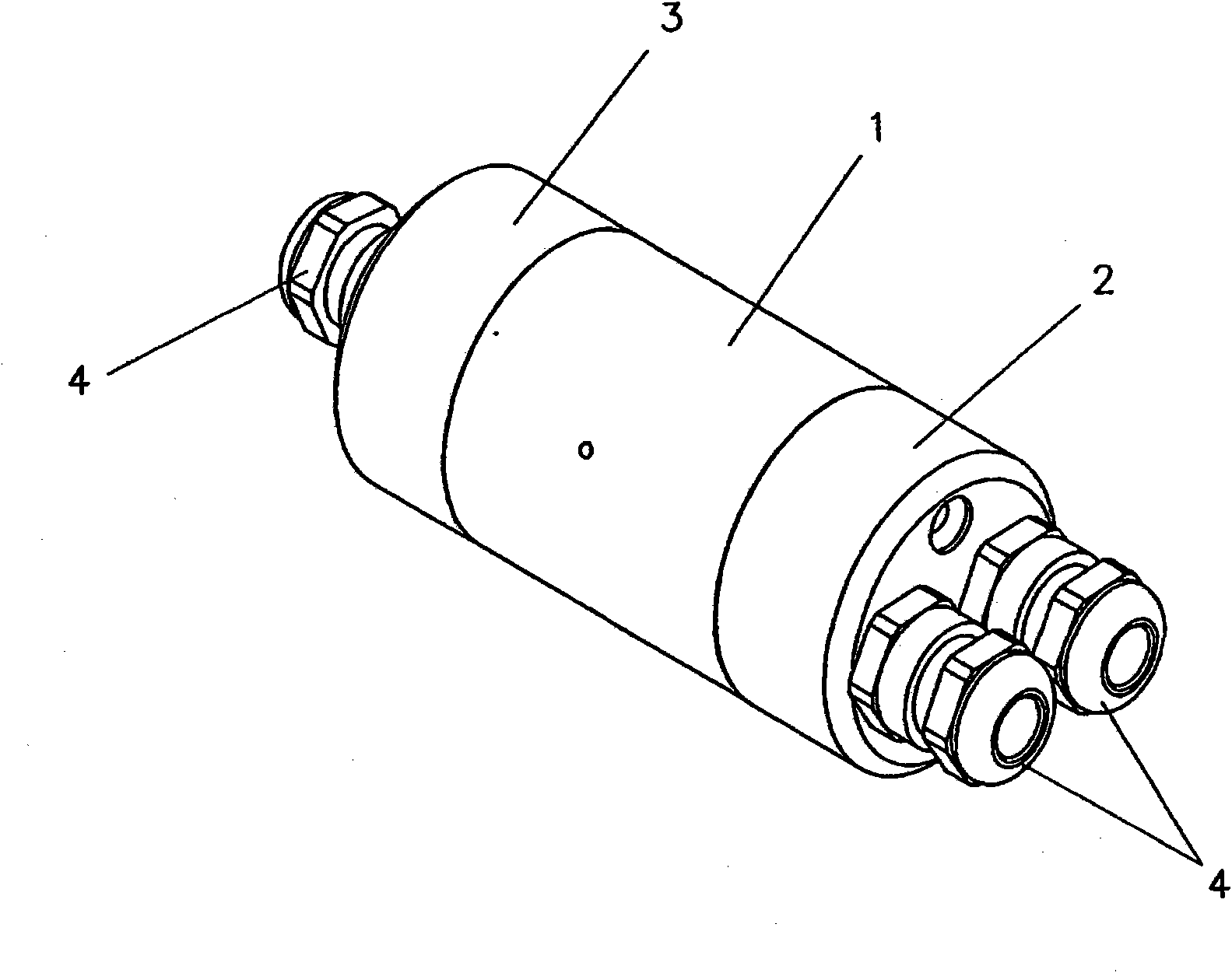
[0025] figure 1 with 2 A first embodiment of an improved connector of the invention is shown, comprising a housing (1) with removable end caps (2 and 3). Each of the removable covers (2 and 3) has at least one cable gland (4) connecting the conductors to the connector.

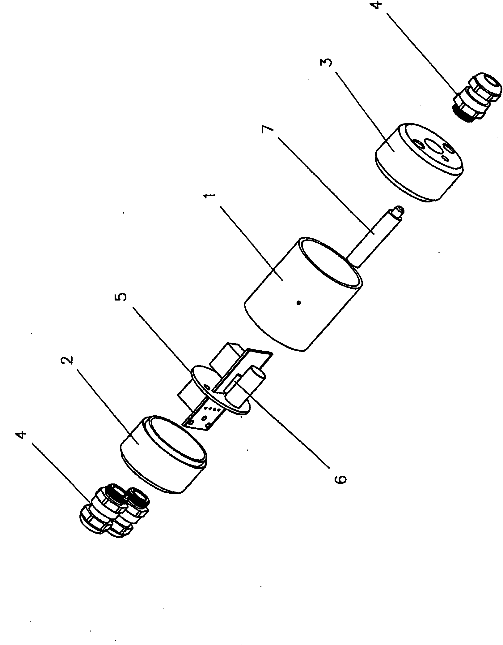
[0026] image 3 with 4 The internal components of the connector are shown in detail, said internal components comprising an internal plate (5) at which conductors are connected, the internal plate (5) comprising conductor connecting bars (51 and 52) and to be fastened to the central support (53) of the housing (1) of the connector, in Image 6 expressed more clearly. The chamber (54) is fastened to the support (53). The reed switches (6) are interconnected on a plate (5) which in turn is interconnected on conductors by bars (51 and 52). In this way, when the reed switch (6) is under the influence of the magnetic field, a signal is passed from one side of the connector to the other.

[0027] On the inpu...


PUM


Abstract

This invention refers to an innovative connector for power grids and / or communication networks which does not cause a spark in the moment it is connected or disconnected. The connector consists of a case (1), with removable end covers (2 and 3). Each one has, at least, one cable gland (4) to connect the conductors to the connector. The connector has an internal board (5), where the conductors are connected, which consists of conductor connection bars (51 and 52) and a central fastening support (53) on the casing (1) of the connector. On the support (53) is fastened a chamber (54). At least one reed switch (6) is connected on the board (5), which in its turn it is connected through the bars (51 and 52) on the conductors. In this way, when the reed switches (6) are under the influence of the magnetic field, the signal passes from one side of the connector to the other. In the first realization of the connector, on the removable input cover (3) is fastened a rod (7) with a magnet at the end (8), which together go into the chamber (54), when the connector is mounted, generating a magnetic field which attracts the reed switch (6) internal filaments connecting or disconnecting them. In the second realization of the connector, a control button (9) operated externally, moves the magnet (8) positioned at the rod end (7) into the chamber (54') which is unified on the central support (531) of the board (5'), generating the magnetic field on the reed switches (6). Through the external operation of the button (9) it is possible to separate or bring together the reed switches (6) to the magnet (8) unified on the rod (7), in such a manner as to switch off or on the connector, respectively without needing to move the removable cover (3).

Description

technical field [0001] The present invention relates to an innovative connector for electrical grids and / or communication networks that does not cause sparks at the moment it is connected or disconnected. Background technique [0002] It is known that special equipment is required in classified plant areas where there is a risk of explosion, such as areas operating in atmospheres contaminated by volatile liquids or flammable particles. Such equipment is explosion-proof and avoids arcing caused by separation or proximity of electrical conductors, which causes ignition of pollutants in the air. [0003] On the other hand, complex industrial facilities (such as oil refineries and similar complex facilities), actuators and other devices are controlled remotely by means of high frequency signals transmitted in communication networks. A control center with processing power automatically controls all installed equipment. [0004] A complication for these facilities is the removal...

Claims


Application Information

Patent Timeline
Patent Type & Authority Applications(China)
IPC IPC(8): H01R13/703
CPCH01R13/7032
Inventor 奥斯卡·汉斯·沃尔夫冈·克斯特尔
Owner 奥斯卡·汉斯·沃尔夫冈·克斯特尔
Learn More