
Electronic load tap switch

An on-load tapping and electronic technology, applied in the direction of electronic switches, circuits, inductors, etc., can solve the problems of short switch life, heavy maintenance workload, long switching time, etc., and achieve good insulation performance, high working reliability, Fast switching effects

Inactive Publication Date: 2004-08-11
蔡长伟
View PDF0 Cites 0 Cited by
  • Summary
  • Abstract
  • Description
  • Claims
  • Application Information

AI Technical Summary

Problems solved by technology

[0002] At present, there are two commonly used on-load tap-changers for domestic power transformers, one is oil-immersed on-load tap-changer; the other is vacuum dry-type on-load tap-changer; they are all contact changeover switches. During the switching process, arc discharge or spark discharge will be generated between the contacts, which makes the life of the switch short, the maintenance workload is heavy, and the switching times and frequency are greatly limited. The above two switches are spring energy storage devices as the operating mechanism. It has complex mechanical structure, high manufacturing process requirements, large switching noise, long switching time, and poor working reliability.

Method used


Image

  • Electronic load tap switch
  • Electronic load tap switch
  • Electronic load tap switch

Examples


Embodiment

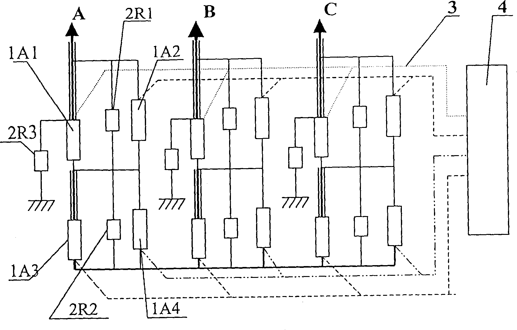
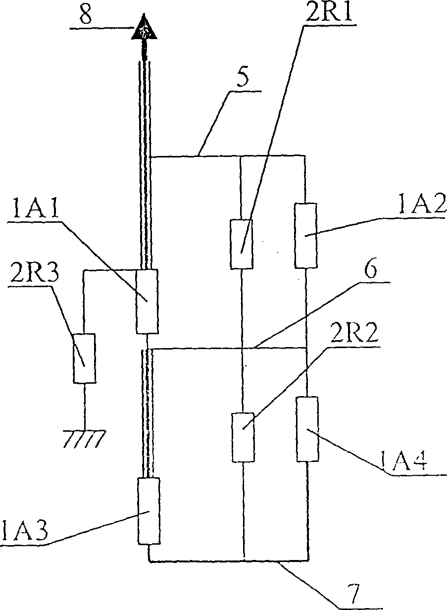
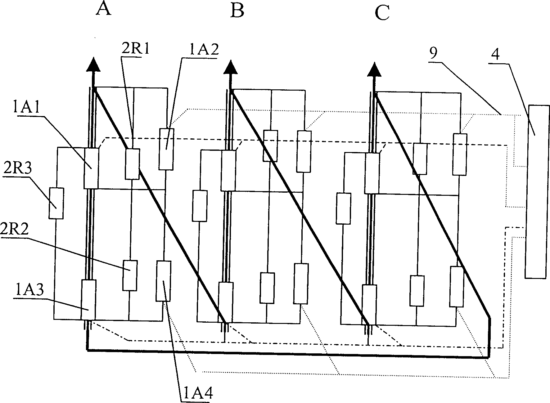
[0014] Example: such as figure 1 , figure 2 , image 3 , Figure 4 As shown, the present invention is an electronic on-load tap-changer, which is a non-contact electronic on-load tap-changer used in conjunction with a transformer, including: solid state relays 1A1, 1A2, 1A3, 1A4, switch switching transition 2R1 , 2R2, 2R3, control board 4, a structure, b structure, A, B, C three-phase, which is characterized in: a structure and b structure solid state relay 1A1, 1A2, 1A3, 1A4, switch transition 2R1, 2R2, 2R3, control board 4, switching structure, A, B, and C three-phase connection structures are all the same, and structure a and structure b each contain:

[0015] a The structure includes: solid state relays 1A1, 1A2, 1A3, 1A4, switch transitions 2R1, 2R2, 2R3, control signal line 3, control board 4, A, B, C three-phase, transformer one split 5, two splits 6, Three branch 7, coil 8, A, B, C three-phase, A, B, C three-phase connection assembly is the same, the right end of ...


PUM


Abstract

An electronic contactless tapping switch for electric power transformer is characterized by use of solid relay. Its advantages are no mechanical operation, electric arc and flutter, high insulating performance and switching speed, small size and low cost.

Description

1. Technical field: [0001] The invention belongs to the field of power system transformer tap changer, in particular relates to an electronic on-load tap changer. 2. Background technology: [0002] At present, there are two commonly used on-load tap-changers for domestic power transformers, one is oil-immersed on-load tap-changer; the other is vacuum dry-type on-load tap-changer; During the switching process, arc discharge or spark discharge will be generated between the contacts, which makes the life of the switch short, the maintenance workload is heavy, and the switching times and frequency are greatly limited. The above two switches are spring energy storage devices as the operating mechanism. It has complex mechanical structure, high manufacturing process requirements, large switching noise, long switching time and poor working reliability. 3. Contents of the invention: [0003] The object of the present invention is to adopt a switching structure in which solid stat...

Claims


Application Information

Patent Timeline
Patent Type & Authority Patents(China)
IPC IPC(8): H01F29/04H03K17/00
Inventor 田胜利蔡长伟霍永德杜宏远
Owner 蔡长伟
Learn More