
Mixed-value based eight-value heat-insulation addition and subtraction counter
A counter and addition and subtraction technology, applied in the field of counters, can solve the problems of high power supply voltage, poor working reliability, high power consumption of eight-value logic circuits, etc.
- Summary
- Abstract
- Description
- Claims
- Application Information
AI Technical Summary
Problems solved by technology
Method used
Image

Examples
Embodiment Construction
[0046] The present invention will be described in further detail below in conjunction with the embodiments of the drawings.
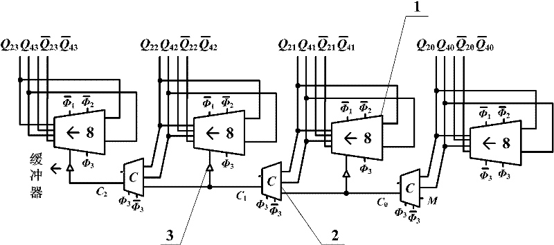
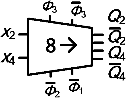
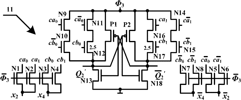
[0047] An eight-value adiabatic addition and subtraction counter based on mixed values (2-4 mixed values), such as Figure 1a As shown, it includes N-bit eight-value trigger adiabatic positive circulation gate 1, N-1 eight-value adiabatic carry / borrow circuit 2 and an eight-value adiabatic carry / borrow circuit set at the i-th bit and the i+1-th eight-value adiabatic carry / borrow circuit. The CTGAL buffer 3 between the value-triggered adiabatic positive circulation gates, the CTGAL buffer makes the phase of the output signal of the i-th octal value adiabatic carry / borrow circuit and the i+1-th octal trigger adiabatic positive circulation gate The phases of the clock-controlled clocks are the same, and each 8-value trigger adiabatic positive circulation gate is connected to the power clock signal with the amplitude level corresponding to logic 1. The amplit...
PUM
 Abstract
Description
Claims
Application Information