Display device and television receiver

A TV receiving device and display device technology, which is applied in the direction of lighting devices, identification devices, electric light sources, etc., can solve the problems of excessive brightness of the display screen, failure to respond to user requirements, and ineffective dimming, etc., and achieve good visual recognition Effect

Inactive Publication Date: 2011-03-02
SHARP KK
View PDF1 Cites 0 Cited by
  • Summary
  • Abstract
  • Description
  • Claims
  • Application Information

AI Technical Summary

Problems solved by technology

However, according to this configuration, the fluorescent lamp cannot be dimmed when the LCD TV is turned on, so there are cases where the brightness of the display screen is too high, or the dimming by the remote control operation becomes ineffective, and it is impossible to respond to the user's use request.

Method used


Image

  • Display device and television receiver
  • Display device and television receiver
  • Display device and television receiver

Examples


Embodiment approach 1

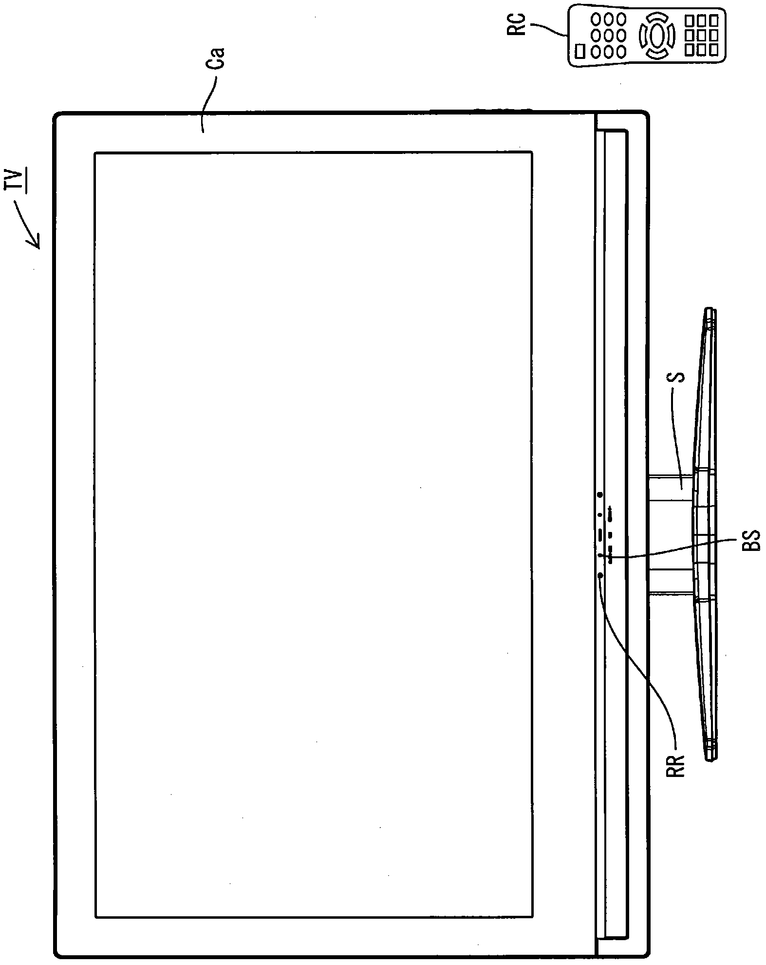
[0064] use Figure 1 to Figure 8 Embodiment 1 of the present invention will be described. In this embodiment, a television receiver TV including a liquid crystal display device 10 as a display device will be described.

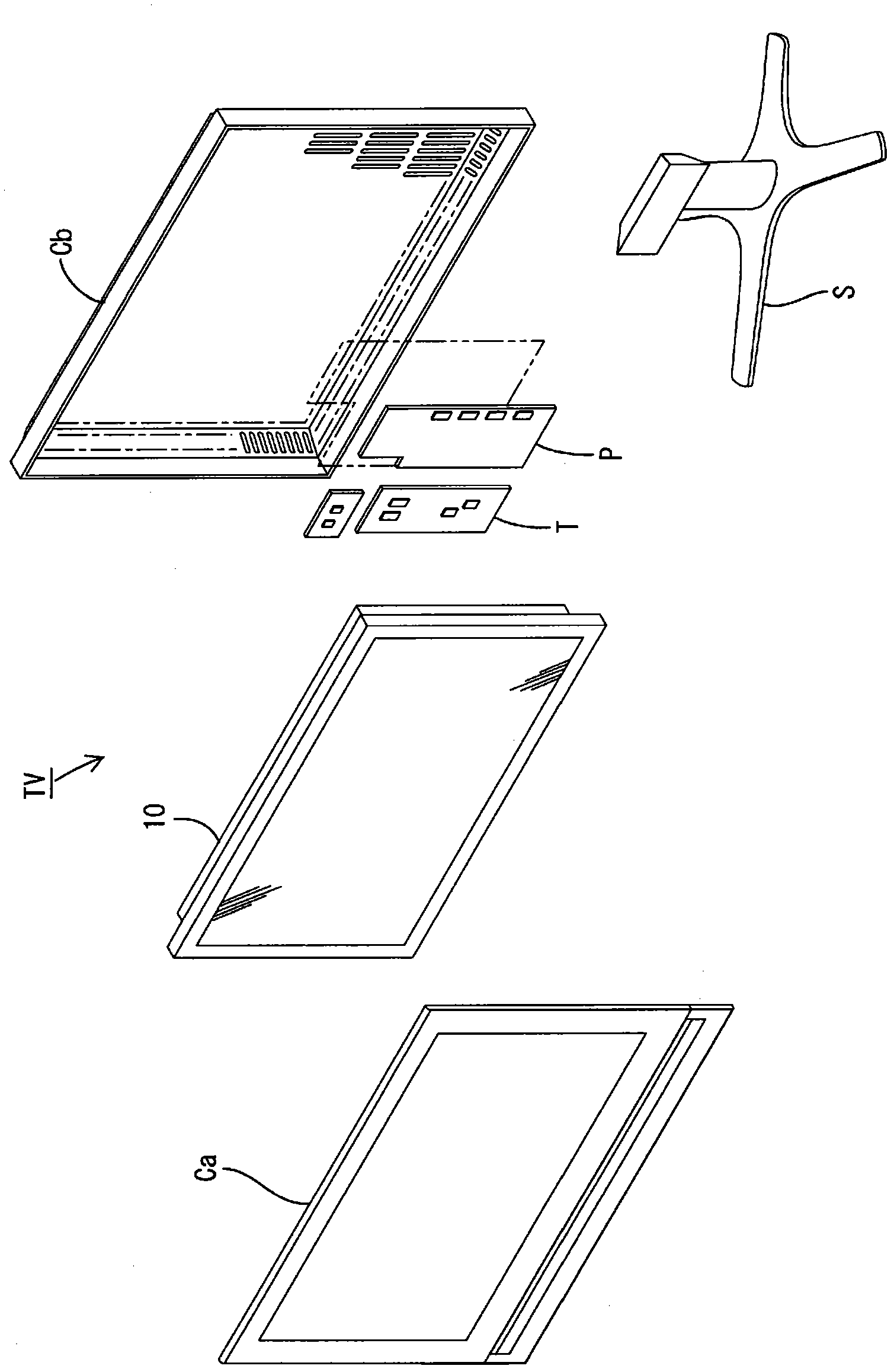
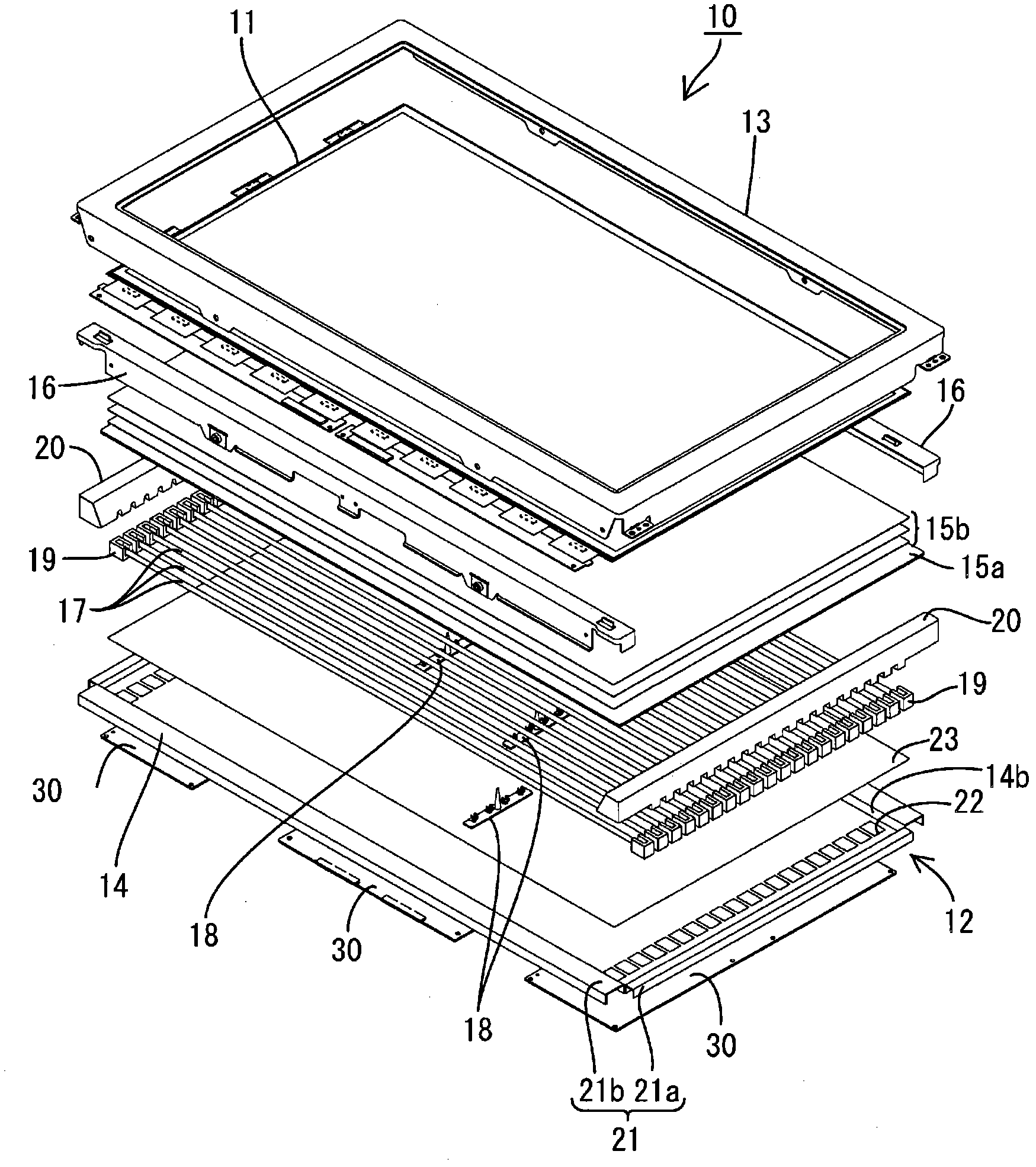
[0065] figure 1 It is a front view showing the structure of the television receiver of this embodiment, figure 2 yes means figure 1 An exploded perspective view of the schematic structure of the television receiver, image 3 yes means figure 1 An exploded perspective view of the schematic structure of the liquid crystal display device included in the TV receiving device of Figure 4 is to mean along image 3 A cross-sectional view of the cross-sectional structure in the short-side direction of the liquid crystal display device, Figure 5 is to mean along image 3 A cross-sectional view of the long-side cross-sectional structure of the liquid crystal display device.

[0066] Such as figure 1 with figure 2 As shown, the television receiver TV of...

Embodiment approach 2

[0110] Below, according to Figure 10 with Figure 11 Embodiment 2 of the present invention will be described. This second embodiment shows a case where the structure of the LUT is changed, and the rest is the same as that of the above-mentioned first embodiment. The same reference numerals are assigned to the same parts as those in Embodiment 1 described above, and overlapping descriptions will be omitted. Figure 10 It is a schematic explanatory diagram showing an example of table contents of a lookup table included in the control board of the liquid crystal display device according to the present embodiment.

[0111] A plurality of LUTs 51 are provided for each total dimming degree. E.g Figure 10 The shown LUT 51 is a table referred to when the total dimming degree is 85 (described in the first column), and the second column describes a temperature list based on the detected temperature TL. According to the LUT 51 of this embodiment, when the detection temperature TL ...

Embodiment approach 3

[0119] pass below Figure 12 with Figure 13 Embodiment 3 of the present invention will be described. In this Embodiment 3, a structure in which dimming can be adjusted by a remote control device is shown, and the rest is the same as that of Embodiment 1 described above. The same reference numerals are assigned to the same parts as those in Embodiment 1 described above, and overlapping descriptions will be omitted.

[0120] Figure 12 It is a block diagram showing the configuration of the dimming control function of the television receiving device according to the present embodiment.

[0121] The television receiver TV of this embodiment has an automatic dimming function that automatically adjusts the brightness of the displayed video according to the brightness of the surroundings detected by the brightness sensor BS, and the user can arbitrarily adjust the brightness of the displayed video by operating the remote control RC.

[0122] The remote control device RC uses the i...


PUM


Abstract

A display device which is provided with a display panel (11) which is capable of gradation display, a fluorescent lamp (17) which emits light to the display panel (11), a dimming control unit (40) for dimming display luminance by controlling the gradation of the display panel (11) and the amount of light emitted from the fluorescent lamp (17), and a temperature sensor (TS) for sensing the temperature of the display device. The display device is characterized in that the dimming control unit (40) conducts control of selecting dimming by the gradation of the display panel (11) or / and dimming by the amount of light emitted from the fluorescent lamp (17) according to the temperature of the display device detected by the temperature sensor (TS).

Description

technical field [0001] The present invention relates to a display device and a television receiver. Background technique [0002] There is known a liquid crystal display device including a non-luminous liquid crystal panel and a backlight device as an illumination device for irradiating light to the liquid crystal panel. When this liquid crystal display device is used as a liquid crystal television, there may be a configuration in which a remote control device used by a viewer to operate the liquid crystal television is attached. The remote control device is usually a device that emits infrared rays. The viewer performs the desired operation on the remote control device, so that the control command is sent to the LCD TV through the infrared signal from the remote control device, and the LCD TV performs channel switching and display brightness according to the control command. Adjustment and other processing. [0003] Sometimes, fluorescent lamps are used as a light source ...

Claims


Application Information

Patent Timeline
Patent Type & Authority Applications(China)
IPC IPC(8): G02F1/133G09F9/00H05B37/02
CPCG09G2320/062G09G3/3648G09G2320/041G09G2330/021G09G2360/144G09G2320/0646G09G3/3406
Inventor 鹰田良树
Owner SHARP KK
Why Eureka
Try Eureka