Structure for improving dark bands of backlight module and method thereof

A technology of backlight module and dark band is applied in the field of improving the structure of the dark band of the backlight module, which can solve the problem of limited effect and achieve the effect of eliminating the dark band.

Active Publication Date: 2012-10-10
苏州茂立光电科技有限公司
View PDF0 Cites 0 Cited by
  • Summary
  • Abstract
  • Description
  • Claims
  • Application Information

AI Technical Summary

Problems solved by technology

[0008] The improvement plan of the patent No. 200739203 published in Taiwan, China is to set a plurality of elongated holes through the two sides of the substrate on the diffuser plate, so that each hole has an arc surface. This design is different from the aforementioned method of using diffusion or focusing. There is no difference in eliminating dark bands, and the effect that can be achieved is really limited

Method used


Image

  • Structure for improving dark bands of backlight module and method thereof
  • Structure for improving dark bands of backlight module and method thereof
  • Structure for improving dark bands of backlight module and method thereof

Examples


Embodiment Construction

[0027] The present invention will be described in further detail below in conjunction with the accompanying drawings and specific embodiments:

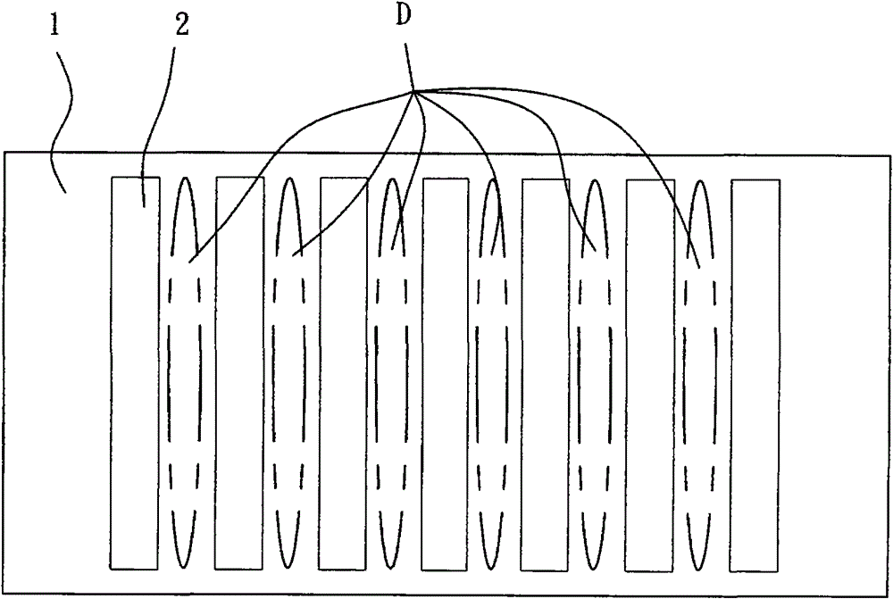
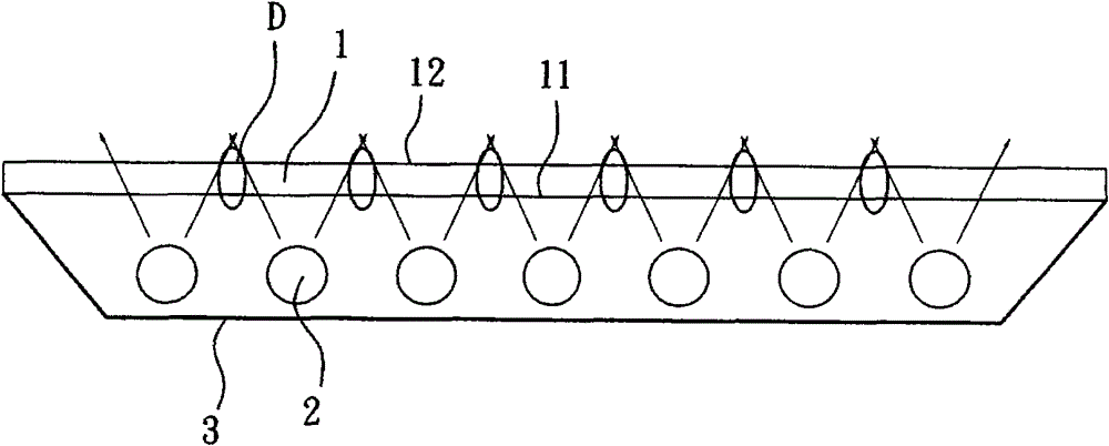
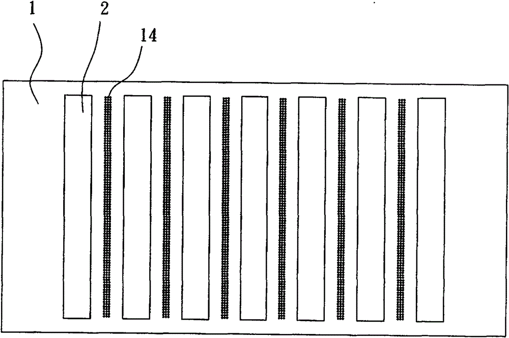
[0028] The feature of the present invention is to improve the structure of the diffuser plate disposed in the backlight module, so that the area between the two light sources with lower light output can obtain more original light sources for compensation, thereby achieving the effect of reducing or even eliminating dark bands.

[0029] The technical means of the present invention is to arrange a plurality of light sources at the position of the backlight module facing the light incident surface of the diffuser plate, wherein the diffuser plate between the two light sources has a plurality of minimum thicknesses smaller than the average thickness of the diffuser plate, so that The original light source with a large amount of light can be emitted from the position of the minimum thickness to make up for the lack of light output in this a...


PUM


Abstract

The invention relates to a structure for improving dark bands of a backlight module and a method thereof, wherein, a plurality of light sources are arranged on an incident light surface of a diffusion plate of the direct backlight module; a plurality of minimum thickness which is less than the average thickness of the diffusion plate are distributed on the diffusion plate between two light sources; and original light sources with greater light quantity are provided from the position of the minimum thickness or original light sources which are relatively more mixed are provided so as to lower or eliminate the dark bands of the diffusion plate generated between two light sources.

Description

technical field [0001] The invention relates to a backlight module, in particular to a structure and a method for improving the dark band of the backlight module. Background technique [0002] At present, the backlight module used as a backlight source can be divided into two types: side light type and direct type according to the projection direction of the light source; the side light type backlight module uses at least one side of the light guide plate as the light incident surface, and the light source enters from the light source. The light surface projects the light into the light guide plate and transmits it, and then reflects the light through the light-emitting surface and the optical film through the reflective sheet symmetrically arranged on the light-emitting surface to produce a luminous effect. [0003] like figure 1 and figure 2 As shown in the figure, for the direct type backlight module, a plurality of light sources 2 are arranged in the inner space of a ...

Claims


Application Information

Patent Timeline
Patent Type & Authority Patents(China)
IPC IPC(8): F21V5/08F21Y103/00
Inventor 苏东权
Owner 苏州茂立光电科技有限公司
Why Eureka
Try Eureka