Thrusting rod bench simulation fatigue tester

A fatigue test, thrust rod technology, applied in the testing of mechanical components, testing of machine/structural components, measuring devices, etc., can solve the problems of long test cycle and low test accuracy

Inactive Publication Date: 2011-03-30
黄衍国
View PDF6 Cites 11 Cited by
  • Summary
  • Abstract
  • Description
  • Claims
  • Application Information

AI Technical Summary

Problems solved by technology

[0002] The role of the thrust rod is to prevent the displacement of the bridge. The general straight thrust rod can only prevent the front and rear displacement of the middle and rear bridges. Fatigue damage is the most important failure form of the mechanical structure, and fatigue is a complicated problem that has not yet been established. Only through the fatigue performance test of the fatigue testing machine can we get more reliable fatigue performance data, but the existing fatigue testing machine has low test accuracy and long test cycle

Method used


Image

  • Thrusting rod bench simulation fatigue tester
  • Thrusting rod bench simulation fatigue tester
  • Thrusting rod bench simulation fatigue tester

Examples


Embodiment Construction

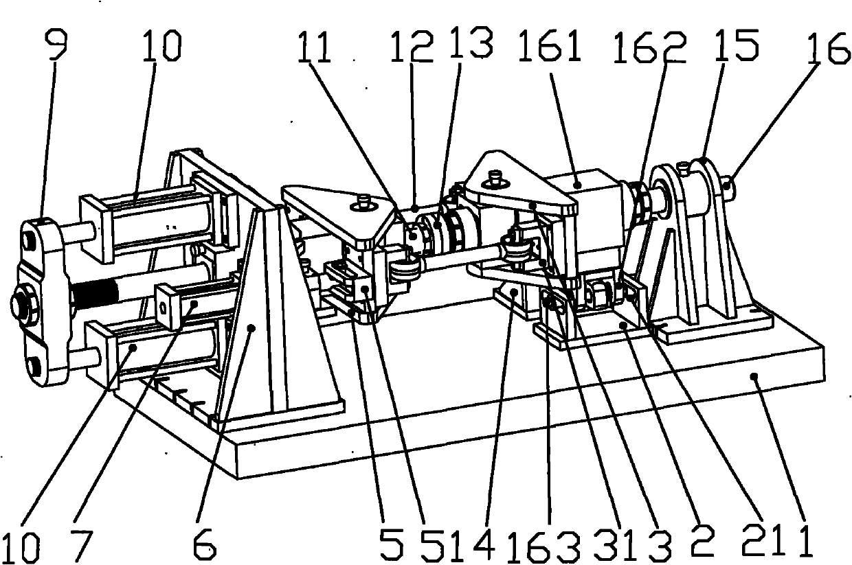
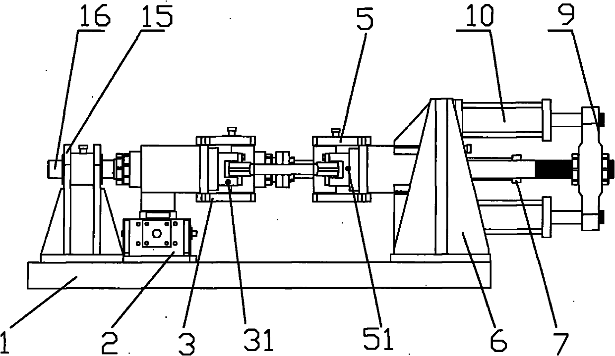
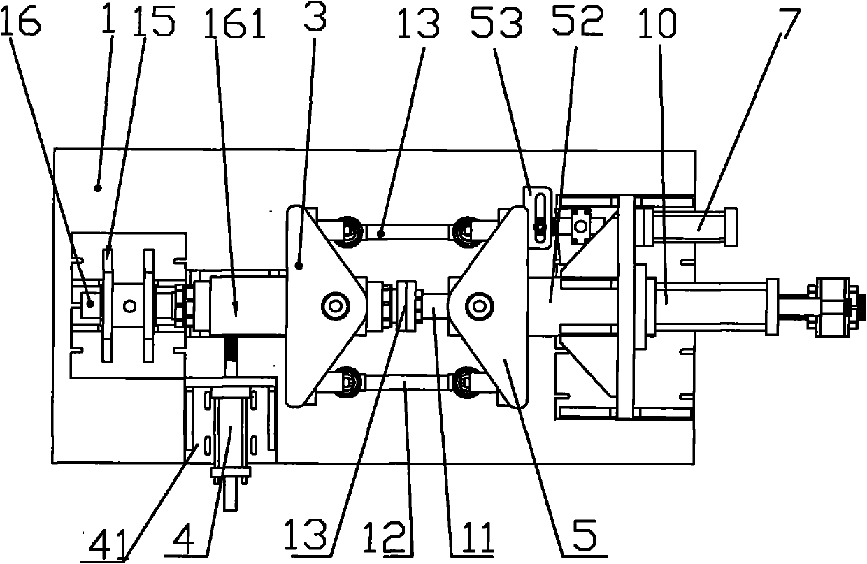
[0012] Such as figure 1 , figure 2 , image 3 As shown, the thrust rod bench simulation fatigue testing machine includes a workbench 1, a front support seat 6 arranged at the front end of the workbench 1, a rear support seat 15 arranged at the rear end of the workbench 1, and a rear support seat 15 mounted on the rear end of the workbench 1. Shaft 16, the front shaft 11 that passes through the front support seat 6, the clutch 13 that is located between the rear shaft 16 and the front shaft 11, the front holder 52 that is located on the inside of the front shaft 11, and the front holder 52 that is located at the inner end of the front holder. Front rotating cam 5, two front U-shaped connection seats 51 located on the left and right sides of the preceding rotating cam 5, the rear fixed seat 161 located on the inside of the rear axle 16, the rear rotating cam 3 located at the rear fixed seat 161 inner end, located at Two rear U-shaped connecting seats 31 on the left and right ...


PUM


Abstract

The invention relates to the field of automobile parts, in particular to a thrusting rod bench simulation fatigue tester, which comprises a work bench, a front support seat arranged at the front end of the work bench, a rear support seat arranged at the rear end of the work bench, a rear shaft penetrating the rear support seat, a front shaft penetrating the front support seat, a clutch arranged between the rear shaft and the front shaft, a front fixing seat arranged on the inner side of the front shaft, a front rotating triangle arranged at the inner end of the front fixing seat, two front U-shaped connecting seats arranged on the left and right of the front rotating triangle, a rear fixing seat arranged on the inner side of the rear shaft, a rear rotating triangle arranged at the inner end of the rear fixing seat, two rear U-shaped connecting seats arranged on the left and right of the rear rotating triangle, and a pulling plate arranged at the outer end of the front shaft. Due to the structure, the simulation fatigue property can be tested, and reliable fatigue property data is acquired; and the property in three directions can be comprehensively tested according to actual road conditions.

Description

technical field [0001] The invention relates to the field of auto parts, in particular to a thrust rod bench simulation fatigue test machine. Background technique [0002] The role of the thrust rod is to prevent the displacement of the bridge. The general straight thrust rod can only prevent the front and rear displacement of the middle and rear bridges. Fatigue damage is the main failure form of the mechanical structure, and fatigue is a complicated problem, which has not yet been established. Only through the fatigue performance test of the fatigue testing machine can we get more reliable fatigue performance data without a clear mathematical model. However, the existing fatigue testing machines have low test accuracy and long test cycle. Contents of the invention [0003] The object of the present invention is a thrust rod bench simulation fatigue testing machine, which can test the simulated fatigue performance and obtain reliable fatigue performance data. [0004] Th...

Claims


Application Information

Patent Timeline
Patent Type & Authority Applications(China)
IPC IPC(8): G01M13/00
Inventor 黄衍国
Owner 黄衍国
Why Eureka
Try Eureka