Piston movement and ignition separated gas power device

A technology of gas power and piston movement, which is applied to internal combustion piston engines, powdered engine fuels, fuel oil systems, etc. It can solve the problems of difficult control of the ignition time of the main charge, complex structure, and single function of the gas power device.

Active Publication Date: 2011-04-06
BEIJING MECHANICAL EQUIP INST
View PDF4 Cites 1 Cited by
  • Summary
  • Abstract
  • Description
  • Claims
  • Application Information

AI Technical Summary

Problems solved by technology

[0003] The purpose of the present invention is to provide a gas power device with separate piston movement and ignition, which solve...

Method used


Image

  • Piston movement and ignition separated gas power device
  • Piston movement and ignition separated gas power device

Examples


Embodiment Construction

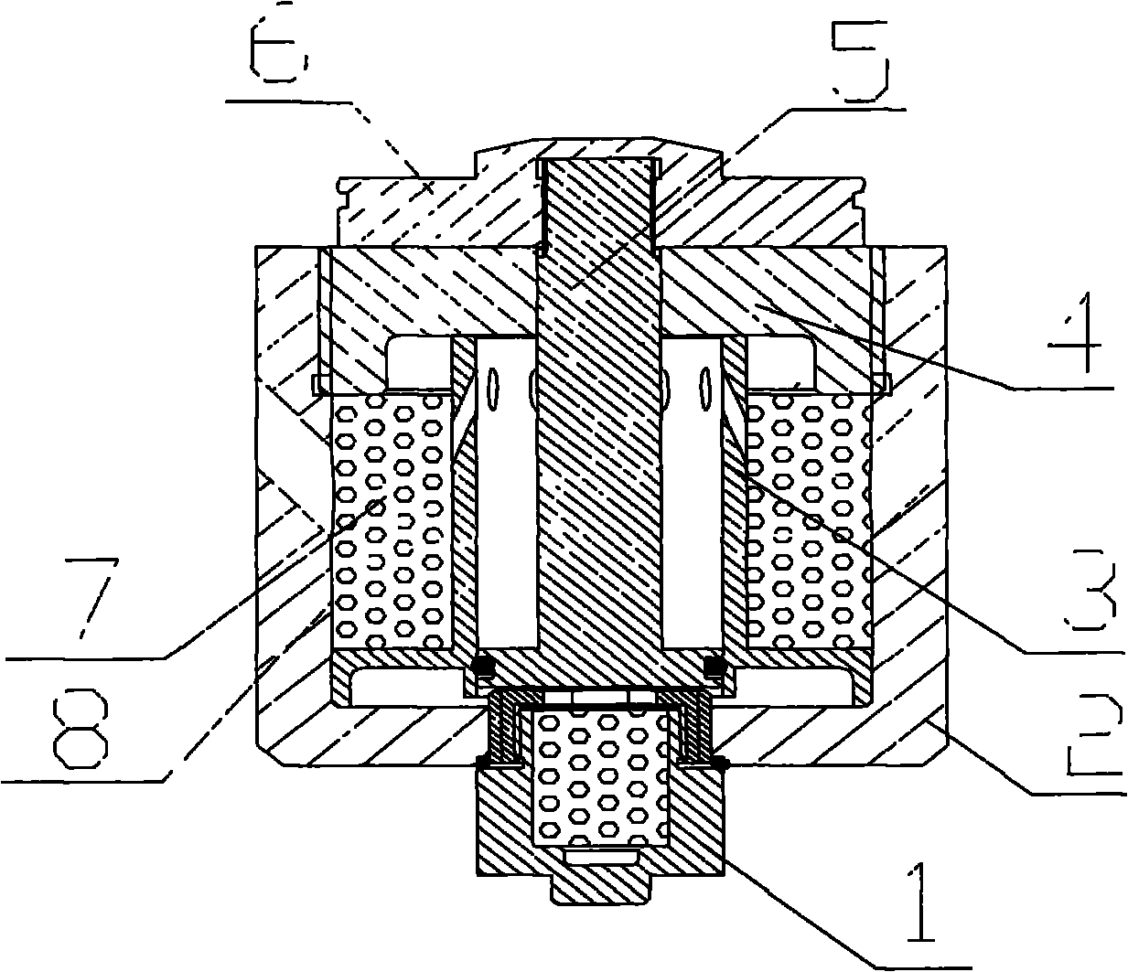
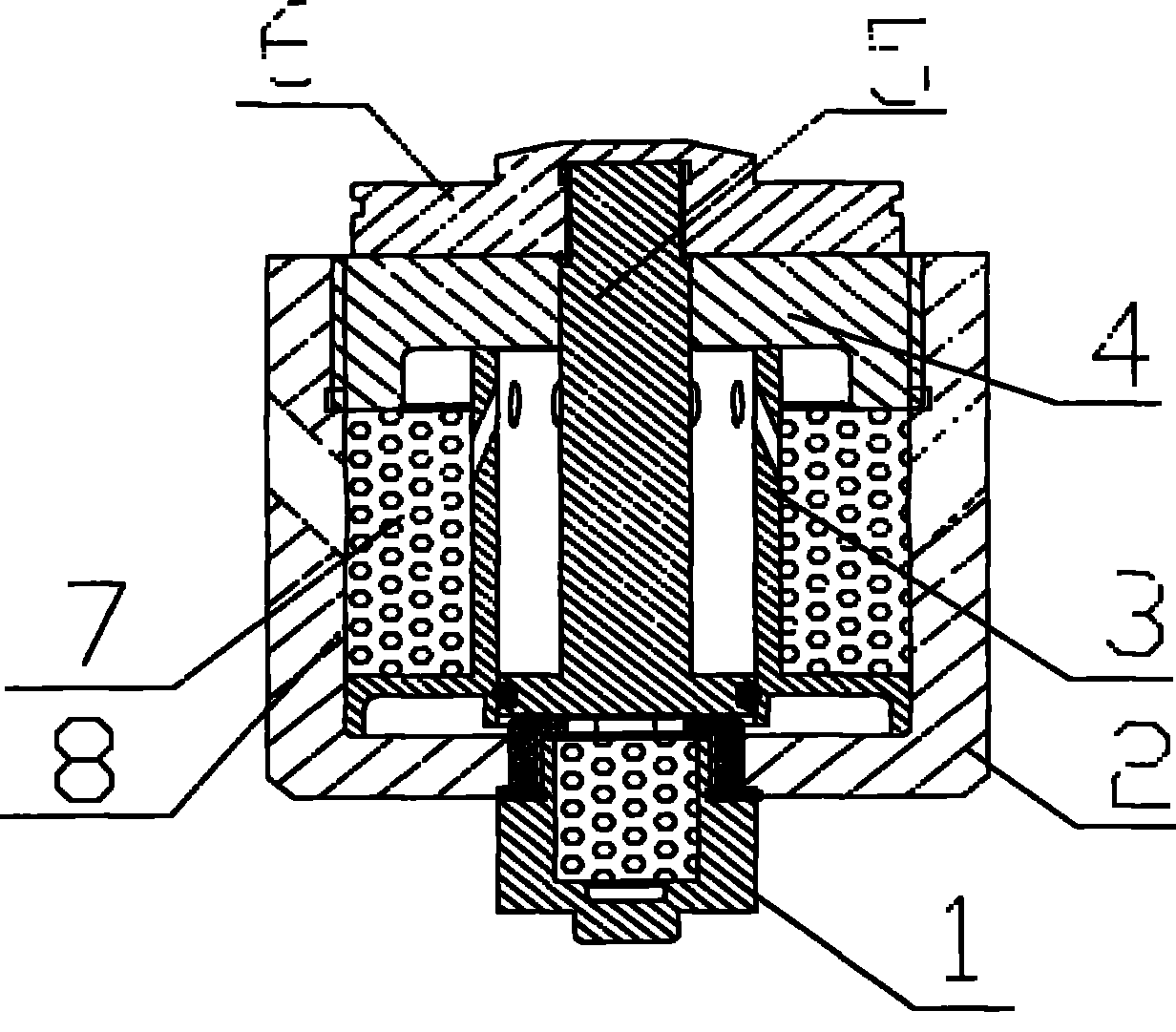
[0009] A gas power device with piston movement and ignition separated, comprising: igniter 1, casing 2, piston top cover 4, piston rod 5, piston head 6, main charge 7, main charge cartridge 8, and also includes: gas Separate sleeve 3. The igniter 1 is screwed on the shell 2, the gas separation sleeve 3 is placed in the inner cavity of the shell 2, the gas separation sleeve 3 and the bottom of the inner wall of the shell 2 are sealed with silicon rubber, the piston rod 5 is placed in the gas separation sleeve 3, The main charge 7 is placed in the main charge cartridge 8, the main charge cartridge 8 is set on the gas separation sleeve 3, the piston top cover 4 is threaded on the top of the casing 2, and the piston head 6 is threaded on the piston rod 5 .

[0010] After the igniter 1 is ignited, a high pressure is formed in the volume between the bottom of the piston rod 5 and the gas separation sleeve 3, pushing the piston rod 5 and the piston head 6 to move upward. With the up...


PUM


Abstract

The invention discloses a piston movement and ignition separated gas power device comprising an igniter (1), a casing (2), a piston top cover (4), a piston rod (5), a piston head (6), main charge (7), a main charge box (8) and a gas separation sleeve (3), wherein the igniter (1) is in threaded connection with the casing (2); the piston rod (5) is arranged in the gas separation sleeve (3); the main charge (7) is arranged in the main charge box (8) which is sleeved on the gas separation sleeve (3); and the piston top cover (4) is in threaded connection with the top of the casing (2). After the igniter (1) is ignited, the piston rod (5) is pushed by the generated gas to upward move; the bottom of the piston rod (5) passes through a ventilation hole of the gas separation sleeve (3); and the main charge (7) is ignited by high-temperature and high-pressure gas. The gas as a power source provides power for the equipment. By changing the length of the piston, the ignition time of the main charge can be controlled by the device more easily and accurately.

Description

technical field [0001] The invention relates to a gas power device, in particular to a gas power device with piston movement and ignition separated Background technique [0002] At present, the gas power devices involved at home and abroad generally include: casing, igniter, igniter, main charge, main charge cartridge, piston rod, piston head and piston top cover, the igniter ignites the igniter, and the igniter generates The gas generated by the main charge is then used to ignite the main charge, and the gas generated by the main charge is used as power to move the piston. This kind of gas power device uses only the gas generated by the igniter and the igniter. The ignition time of the charge is not easy to control. Contents of the invention [0003] The object of the present invention is to provide a gas power device with piston movement and ignition separated, which solves the problems of single function, complex structure and difficult control of the ignition time of ...

Claims


Application Information

Patent Timeline
IPC IPC(8): F02B45/02
CPCY02T10/34Y02T10/30
Inventor 韩书永迟克刚
Owner BEIJING MECHANICAL EQUIP INST
Why Eureka
Try Eureka