Supercharge Your Innovation With Domain-Expert AI Agents!

Circuit breaker

A circuit breaking, disconnector technology, applied in circuits, switches operated by ground fault currents, electrical components, etc., to solve problems such as electromagnetic coil burnout

Active Publication Date: 2013-01-16
KAWAMURA ELECTRIC INC
View PDF2 Cites 0 Cited by
  • Summary
  • Abstract
  • Description
  • Claims
  • Application Information

AI Technical Summary

Problems solved by technology

Therefore, after the main circuit is disconnected, if you continue to press the test switch inadvertently, the electromagnetic coil may be burned

Method used


Image

  • Circuit breaker
  • Circuit breaker
  • Circuit breaker

Examples


Embodiment Construction

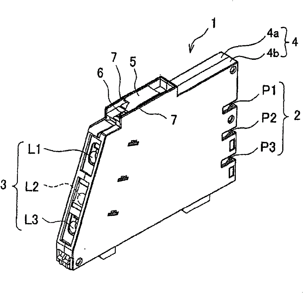
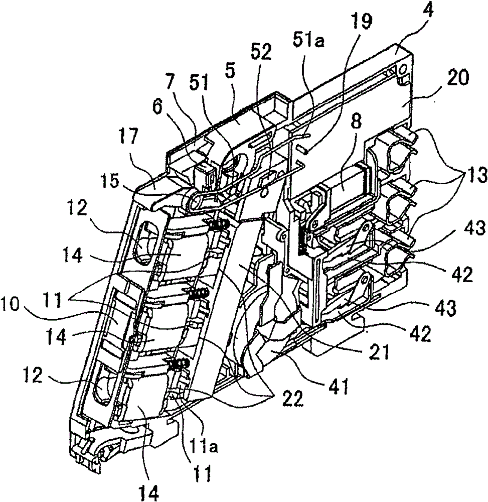
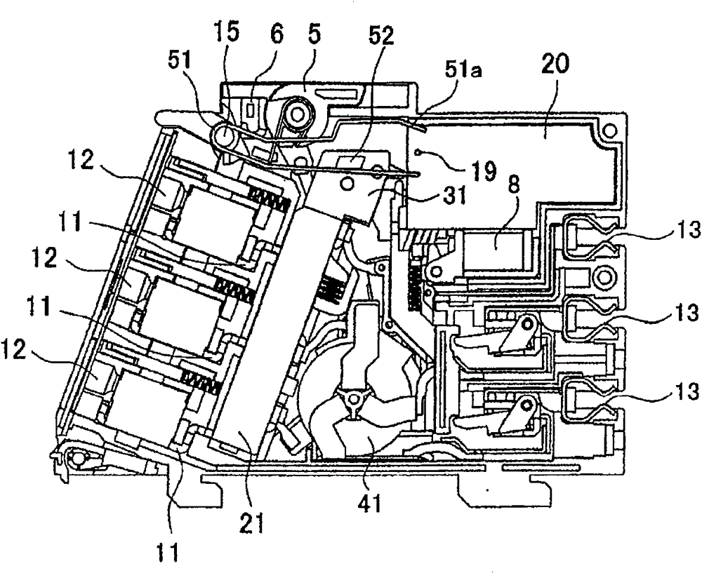
[0041] Next, an embodiment in which the circuit breaker of the present invention is realized will be described with reference to the drawings. figure 1 It is a perspective view showing the appearance of the circuit breaker. figure 2 It is a perspective view showing the internal mechanism of the circuit breaker when the main circuit is turned on by the operating handle. image 3 It is a side view showing the internal mechanism in the same ON state. Figure 4 It is a side view showing the inside of the separator in the same ON state. Figure 5 It is a perspective view showing the internal mechanism with the main circuit cut off by the operating handle. Figure 6 It is a side view showing the internal mechanism in the same cut-off state. Figure 7 It is a side view showing the inside of the separator in the same cut state. Figure 8(a) is an enlarged side view showing a part of the circuit breaker in a state where the test switch has disconnected the test circuit. Figure 8...


PUM


Abstract

To provide a circuit breaker which can meet the needs for downsizing or thinning of a housing. In the circuit breaker (1), when the a leakage detection circuit on a print substrate (20) detects the leakage of a main circuit, a trip coil (8) acts and a separator (21) rises to cut off the main circuit. A test circuit is arranged on the print substrate (20) for testing action of the trip coil (8) and etc. by enabling the doubtful leakage state. A U-shaped test switch (51) for turning on and off the test circuit is configured to be crossed with the separator. When the separator (21) moves to the direction of turning off the main circuit, a projection (52) of the separator (21) forces to release the on state of the test switch (51) and forbids the on operation of the test switch (51).

Description

[0001] This application is a divisional application of an invention patent application with an application date of August 10, 2007, an application number of 200710140840.8, and an invention title of "circuit breaker". technical field [0002] The present invention relates to circuit breakers provided, for example, in switchboards. Background technique [0003] Conventionally, there is known a circuit breaker that, when a leakage in a main circuit is detected, operates a disconnection mechanism to move a separator within a disconnector case, thereby disconnecting the main circuit. In addition, there is also known a circuit breaker provided with a test circuit for testing whether or not the breaking mechanism operates normally when an electric leakage occurs. Since the test circuit generally secures power from the load-side circuit of the circuit breaker, even if the test switch is turned on, a suspected leakage current flows through the test circuit and the main circuit is di...

Claims


Application Information

Patent Timeline
Patent Type & Authority Patents(China)
IPC IPC(8): H01H83/04
CPCH01H71/04H01H83/04H01H2217/046
Inventor 加藤裕明
Owner KAWAMURA ELECTRIC INC
Features
  • R&D
  • Intellectual Property
  • Life Sciences
  • Materials
  • Tech Scout
  • Unparalleled Data Quality
  • Higher Quality Content
  • 60% Fewer Hallucinations
Learn More