Check patentability & draft patents in minutes with Patsnap Eureka AI!

Processes and Device for Low Temperature Separation of Air

A technology for separating air and low temperature, applied in lighting and heating equipment, cold treatment separation, refrigeration and liquefaction, etc., can solve problems such as turbine damage, and achieve the effect of low equipment cost and high efficiency

Inactive Publication Date: 2011-04-20
LINDE AG
View PDF6 Cites 10 Cited by
  • Summary
  • Abstract
  • Description
  • Claims
  • Application Information

AI Technical Summary

Problems solved by technology

Higher liquid fraction can lead to turbine damage

Method used


Image

  • Processes and Device for Low Temperature Separation of Air
  • Processes and Device for Low Temperature Separation of Air
  • Processes and Device for Low Temperature Separation of Air

Examples


Embodiment Construction

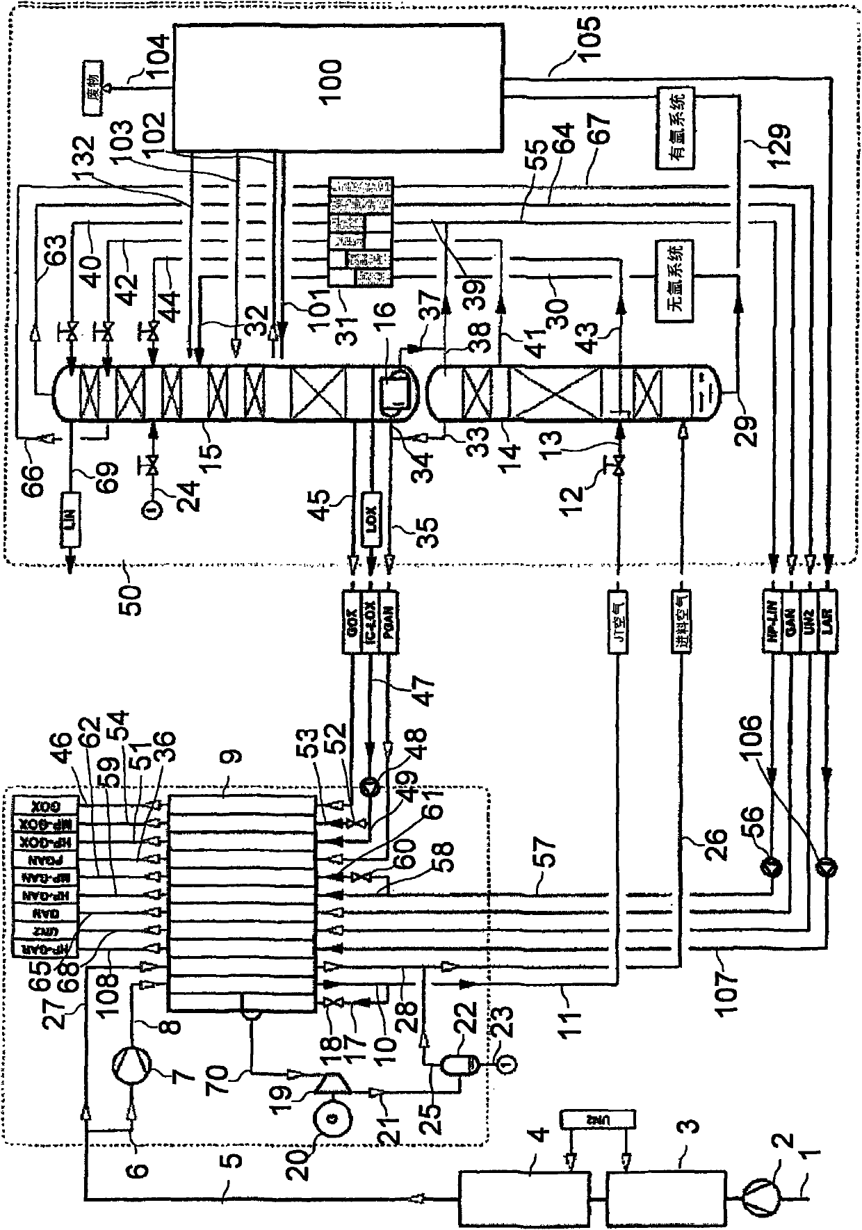
[0029] exist figure 1 In the embodiment of the present invention, the distillation column system 50 has a high-pressure column 14, a low-pressure column 15 and a main condenser 16 configured as a condenser-evaporator in the part for the separation of nitrogen and oxygen, and the two columns pass through the main condenser form a heat exchange relationship.

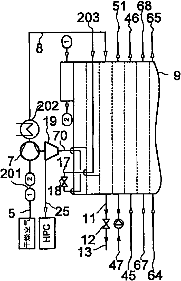
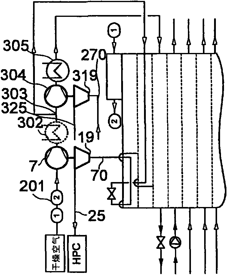
[0030] Atmospheric air is sucked in as the main air flow via line 1 by an air compressor 2, raised there to a first pressure substantially equal to the operating pressure of the high-pressure column 14, cooled in a precooler 3 to approximately ambient temperature and Supply to an adsorption air cleaning device 4. A first part of the cleaned main air flow 5 is recompressed in a recompressor 7 to a second pressure of at least 50 bar, for example approximately 60 bar, as "first air flow 6". The high pressure air 8 is led to the hot end of the main heat exchanger 9 where it is cooled and pseudo-liquefied. The pseudo-liquefi...


PUM


Abstract

Processes and a device for the low-temperature separation of air are provided. A main air stream is compressed in an air compressor at a first pressure and is then purified. A first air stream is further compressed at a second pressure. From the further compressed first air stream, a throttling stream and a turbine stream are branched off. The throttling stream is cooled down and liquefied or pseudo-liquefied for supply to an expansion device and is then conducted into a distillation-column system via the expanded throttling steam. The turbine stream is cooled down in the main heat exchanger, under an intermediate temperature of the main heat exchanger is conducted into an expansion machine, as well as works and expands. The worked expanded turbine stream is at least partially conducted to the distillation-column system. The liquid product flow is withdrawn, the liquid improves to an increased pressure, evaporates or pseudo-evaporates under the pressure, and is withdrawn as a gas state product flow. The turbine flow is cooled in a main heat exchanger so that dew-point temperature or low temperature is achieved when pressure of the turbine flow is sub-critical. The turbine flow liquefied or pseudo-liquefied or is expanded to intermediate pressure that lies between a first pressure and a second pressure. The expanded turbine flow in the main heat exchanger is heated to intermediate temperature before the turbine flow is fed to an expansion machine.

Description

technical field [0001] The invention relates to a method according to the preamble of claim 1 . Background technique [0002] These processes, in which a liquid pressurized product stream is evaporated against a heat carrier and finally recovered as a gaseous pressurized product, are also referred to as internal compression methods. It is used in particular to obtain pressurized oxygen, but it can also be used to obtain pressurized nitrogen or pressurized argon. The phase transfer does not take place in the true sense for supercritical pressure conditions in the main heat exchanger, so the product stream "pseudo-vaporizes". [0003] In the main heat exchanger, a partial flow of the heat carrier at high pressure, namely air, referred to here as "throttling flow", is liquefied against the (pseudo) vaporized product flow (or pseudo- liquefaction). [0004] It is customary here that the throttle flow and the turbine flow are raised together in a recompressor or in a main air ...

Claims


Application Information

Patent Timeline
Patent Type & Authority Applications(China)
IPC IPC(8): F25J3/04
CPCF25J3/04084F25J3/04393F25J2240/42F25J3/04315F25J2240/04F25J3/04296F25J2240/44F25J3/04303F25J3/04096F25J3/0409F25J2240/46F25J3/04309F25J3/04054F25J3/04175F25J3/04412F25J2270/02F25J3/04648F25J2205/04F25J2215/54F25J3/04781F25J3/04375F25J2240/10F25J3/04666
Inventor A·阿列克谢耶夫
Owner LINDE AG
Features
  • R&D
  • Intellectual Property
  • Life Sciences
  • Materials
  • Tech Scout
  • Unparalleled Data Quality
  • Higher Quality Content
  • 60% Fewer Hallucinations
Learn More