
Method and system for determining a force acting on a body

A technology of objects and functions, applied in the direction of measuring force components, fluid velocity measurement, aerodynamic tests, etc., can solve problems such as measurement results errors

Inactive Publication Date: 2013-07-31
AIRBUS OPERATIONS GMBH
View PDF0 Cites 0 Cited by
  • Summary
  • Abstract
  • Description
  • Claims
  • Application Information

AI Technical Summary

Problems solved by technology

This can only be achieved at the expense of considerable technical complexity
In addition, centrifugal forces generated during rotation can lead to erroneous measurements

Method used


Image

  • Method and system for determining a force acting on a body
  • Method and system for determining a force acting on a body
  • Method and system for determining a force acting on a body

Examples


Embodiment Construction

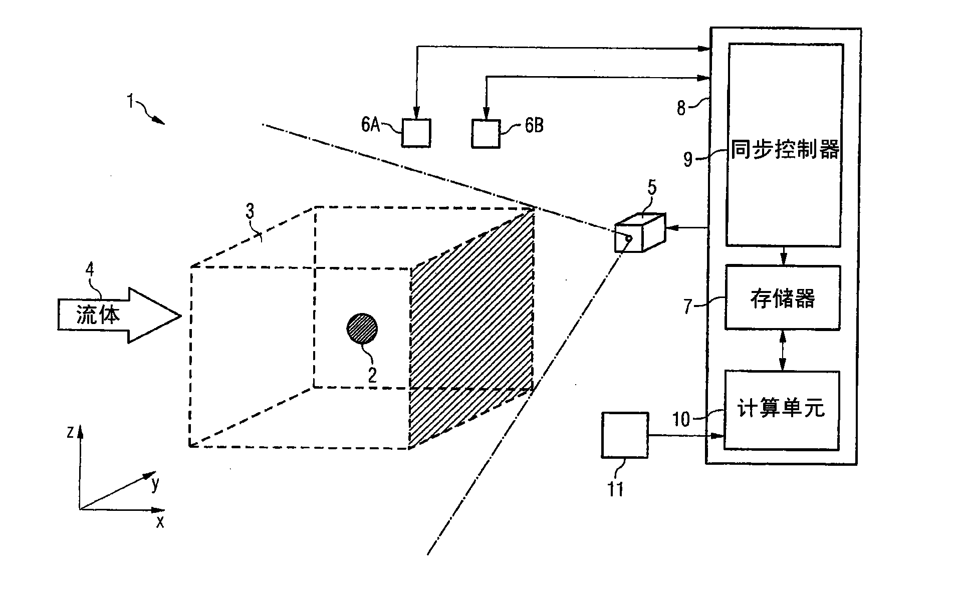
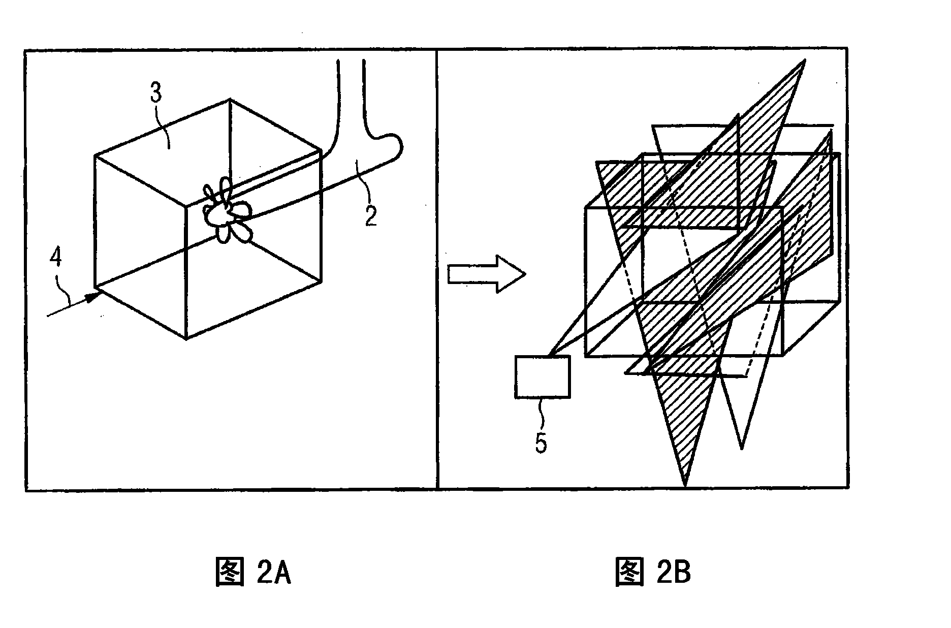
[0054] From figure 1 As can be seen in the measurement system 1 according to the invention, an object 2 is placed in a controlled volume 3 provided in a flow channel or a wind tunnel. Object 2 may be any desired object, in particular a three-dimensional model. A three-dimensional model is, for example, a model of an aircraft or an aircraft component. Object 2 can also be any other object to be studied, for example, a vehicle or a building to be studied. The object 2 to be investigated is in the controlled volume, ie the volume or size of the object 2 is smaller than the controlled volume 3 . The controlled volume 3 within the flow channel is a closed volume and has a plurality of defined surfaces. The geometry of the controlled volume 3 can be chosen according to the geometry of the object 2 to be investigated. Preferably, the coordinates of the defined surface of the controlled volume are stored in a memory to control the measuring device. exist figure 1 In the shown em...


PUM


Abstract

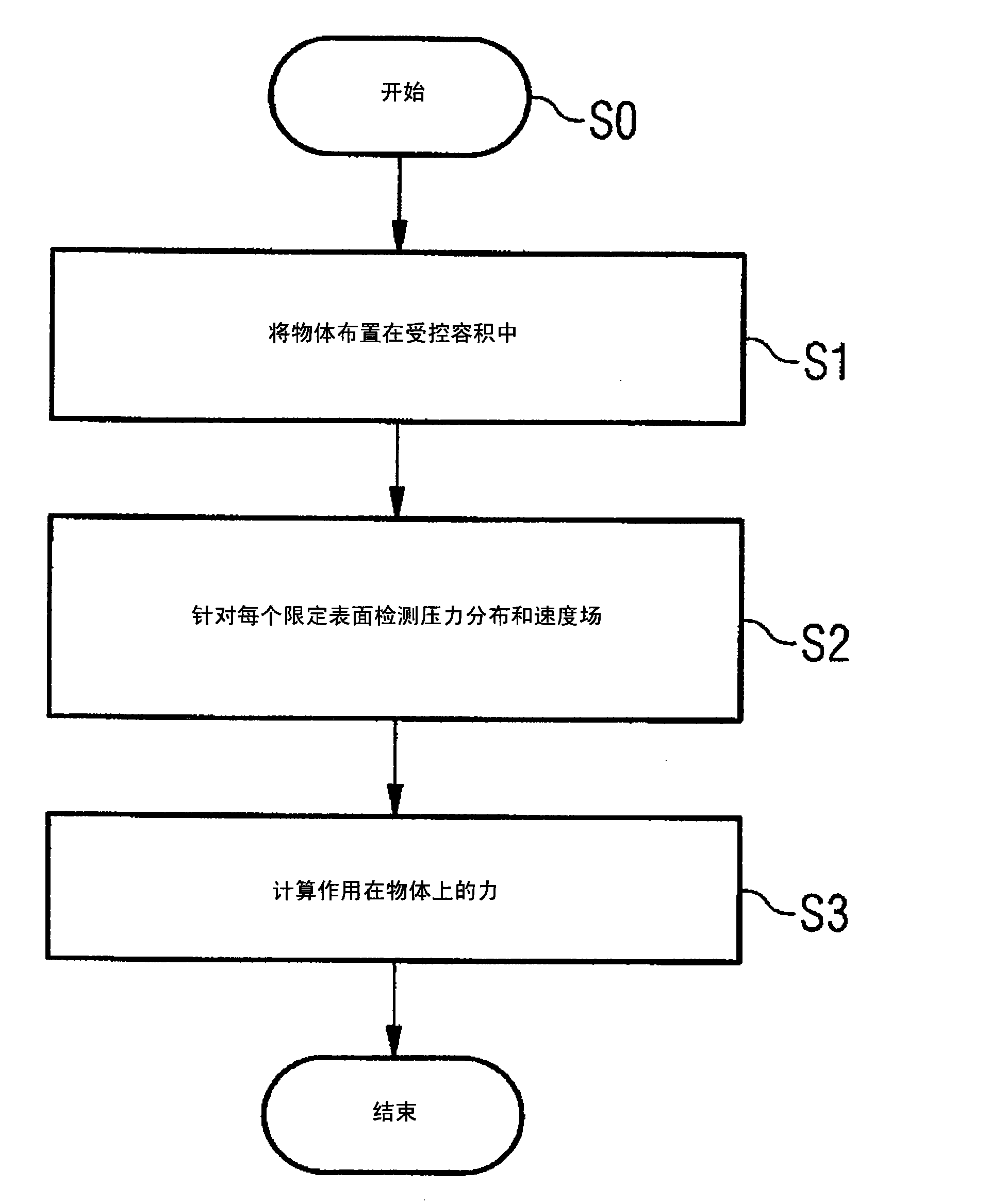
The present invention provides a method and a system for determining forces which act on a body with a controlled volume which is provided inside the flow tunnel and in which the body is arranged. A first measuring means is used to measure a pressure distribution for each surface defining the controlled volume. A second measuring means measures a velocity field for each defining surface of the controlled volume. Furthermore, a calculation unit is provided for calculating the forces acting on the body as a function of the pressure distributions and velocity fields measured for the defining surfaces of the controlled volume.

Description

Background technique [0001] In order to study the aerodynamic and aeroacoustic properties of an object, a true scale three-dimensional model of the object or object to be studied is placed in a wind tunnel or flow tunnel. For example, a model of an airplane or other vehicle is arranged in a flow channel to be exposed to fluid flow, such as air flow. In addition to studying models of vehicles, runners can also be used to study buildings. In this regard, a three-dimensional model of a building, such as a multi-storey building or a bridge, is arranged in a wind tunnel and exposed to air currents. [0002] Due to the limited diameter of the runners, objects are rarely studied in the runners at their actual size. For this reason, realistic scale three-dimensional models are usually made of large objects and arranged in flow channels to study the flow behavior of the objects. [0003] For objects, especially aircraft, it is important when studying the aerodynamic behavior of the ...

Claims


Application Information

Patent Timeline
Patent Type & Authority Patents(China)
IPC IPC(8): G01L5/16G01M9/06G01P5/26
CPCG01M9/067G01M9/065G01L5/16G01P5/001G01L5/171
Inventor 埃里克·威勒马斯·玛丽亚·罗森布姆安德里斯·施罗德尔克劳斯-彼得·内茨柯温弗里德·库恩
Owner AIRBUS OPERATIONS GMBH
Learn More