
Method and arrangement for determining the dispersion of an optical transmission link

An optical transmission and line technology, which is used in measurement devices, transmission systems, electromagnetic wave transmission systems, etc.

Inactive Publication Date: 2006-04-12
NOKIA SIEMENS NETWORKS GMBH & CO KG
View PDF3 Cites 2 Cited by
  • Summary
  • Abstract
  • Description
  • Claims
  • Application Information

AI Technical Summary

Problems solved by technology

But the disadvantage of the described method is that the measurements cannot be performed during data transmission in the optical network
Measurements can only be carried out in a separate optical transmission line with a receiver with network analyzer and additional evaluation unit

Method used


Image

  • Method and arrangement for determining the dispersion of an optical transmission link
  • Method and arrangement for determining the dispersion of an optical transmission link
  • Method and arrangement for determining the dispersion of an optical transmission link

Examples


Embodiment Construction

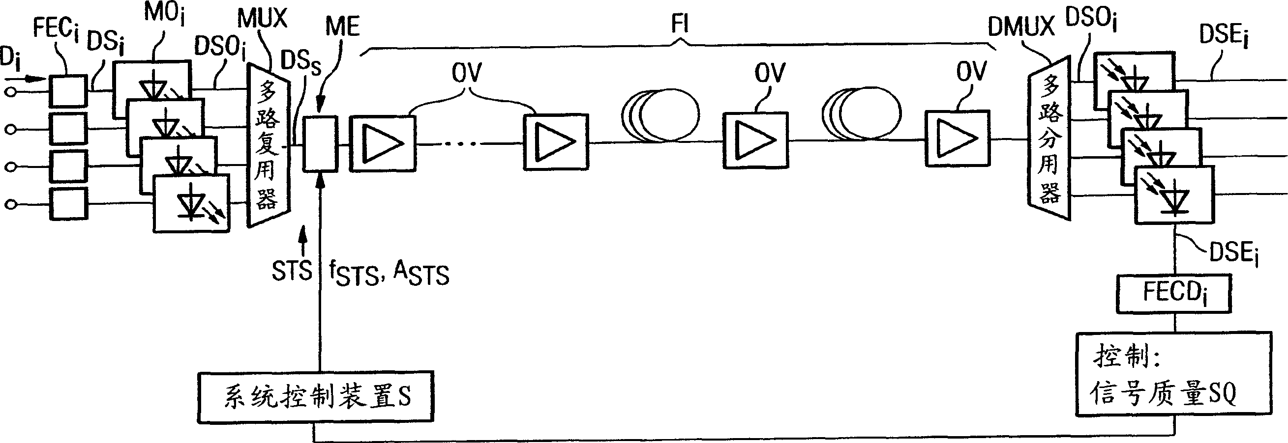
[0021] in like figure 1 In the optical transmission line schematically shown in , the data signal D to be transmitted i First in the FEC encoder FEC i protected in. Then multiple optical carrier signals in the modulator MO i The coded data signal DS is used within i modulation, and the optical data signal DSO i Compiled into a multiplexed signal DS on the transmit side by the multiplexer MUX S . All optical data signals DS output by the multiplexer MUX S Together, they are modulated (preferably amplitude modulated) in the modulation unit ME to form a sinusoidal interference signal STS. The term "modulation" here is also intended to include the same effect caused by superposition. The signal quality thus deteriorates and the number of bit errors to be corrected by FEC increases. Interfering signal STS not only at frequency f STS and at amplitude A STS above can be changed. The two modulation parameters are adjusted using the system controller S. After passing throu...


PUM


Abstract

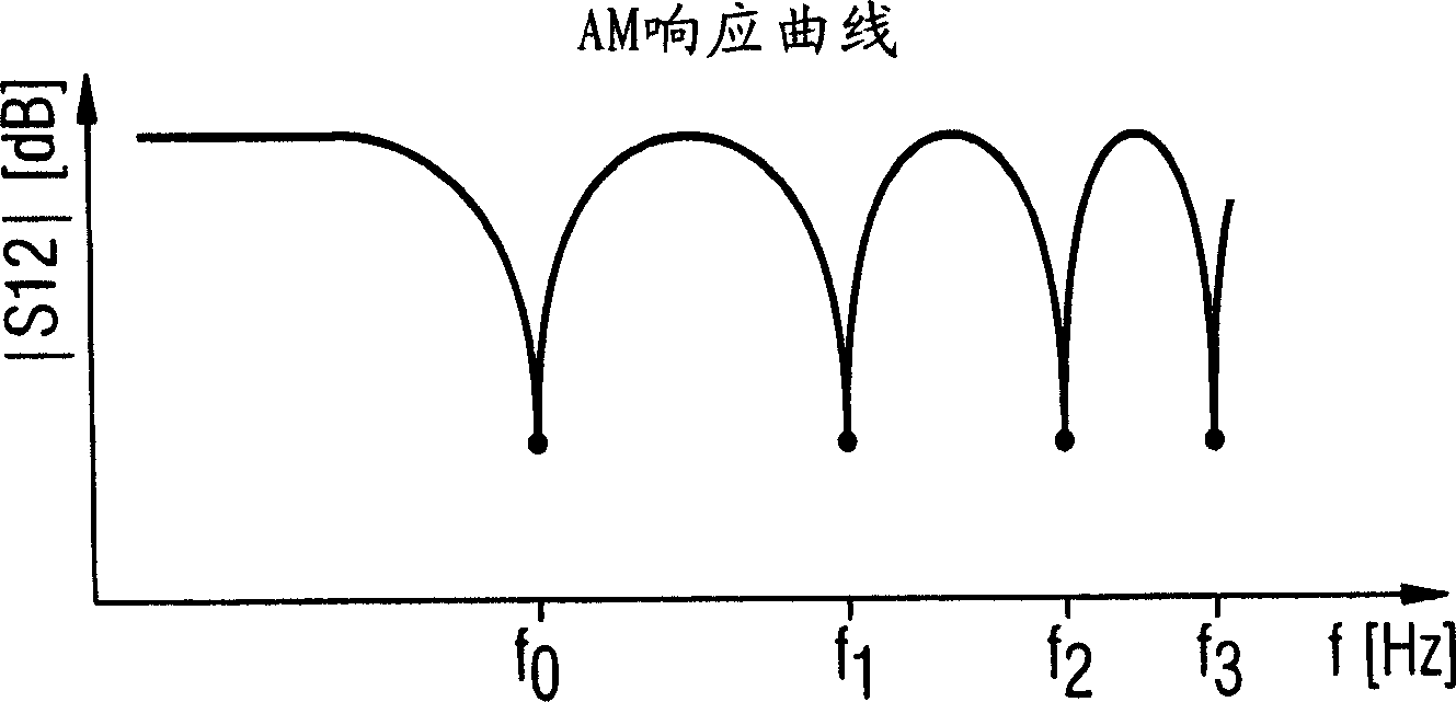
The invention relates to a method and an arrangement for determining the dispersion of an optical transmission link. By determining the signal quality, the bit error rate is measured for a modulated data signal depending on the modulation frequency of a noise signal (STS). The dispersion coefficient of the transmission link is calculated on the basis of the resulting discrete minima of the bit error rates. These measurements can take place advantageously during the operation of the data transmission. The method also provides additional information about the quality of the data transmission by determining the non-linear phase shift.

Description

technical field [0001] The invention relates to a method according to the preamble of claim 1 and a device according to the preamble of independent claim 9 . Background technique [0002] The effective distance and capacity of optical transmission lines of telecommunications technology are also limited, among other things, by signal distortions due to dispersion in the transmission fibers. Often used standard single-mode fiber (SSMF) has a dispersion coefficient of about 17 ps / (nm*km) in a wavelength window around 1550 nm. With a channel data rate of 2.5 GBit / s, a dispersion-limited regenerator spacing of approximately 1000 km can be achieved without compensation measures. Since the effective distance decreases in inverse proportion to the square of the channel data rate, regenerator distances of approximately 70 km and approximately 3 km respectively result in the case of 10 GBit / s and 40 GBit / s. Therefore, for most 10GBit / s systems and actually all 40GBit / s systems, it i...

Claims


Application Information

Patent Timeline
Patent Type & Authority Applications(China)
IPC IPC(8): G01M11/00H04B10/08
CPCG01M11/338G01M11/335
Inventor E·戈特瓦德
Owner NOKIA SIEMENS NETWORKS GMBH & CO KG
Learn More