Surge suppression circuit

A surge suppression circuit and resistor technology, applied in circuit devices, emergency protection circuit devices, emergency protection circuit devices for limiting overcurrent/overvoltage, etc., can solve the problem of increased drain current and increased conduction of MOS transistors. , can not be further increased, etc., to reduce power loss, suppress surge voltage, and ensure stable operation.

Inactive Publication Date: 2011-06-01
MORNSUN GUANGZHOU SCI & TECH
View PDF4 Cites 39 Cited by
  • Summary
  • Abstract
  • Description
  • Claims
  • Application Information

AI Technical Summary

Problems solved by technology

The gate and drain are connected as one end, and the source is used as one end, which is equivalent to a Zener diode. Taking an N-channel MOS transistor as an example, the gate and drain are connected as one end, and the source is used as one end, that is, V GS =V DS When the gate and drain terminals are connected to the positive power supply, the source is connected in series with the current limiting resistor and the power supply is negative. At the beginning, the MOS tube is not turned on, and the power supply voltage is raised. This voltage is greater than the turn-on voltage of the MOS tube ( Gate threshold voltage), the MOS tube starts to conduct, and a drain current is generated, due to V GS =V DS , this voltage cannot be further increased, once the voltage increases due to some reason, then V GS Synchronous rise, that is, the gate-to-source voltage rises, the conduction of the MOS transistor is further increased, and the drain current increases sharply, making V DS falling, gate and drain connected together, V GS synchronous fall

Method used


Image

  • Surge suppression circuit
  • Surge suppression circuit
  • Surge suppression circuit

Examples


Embodiment 1

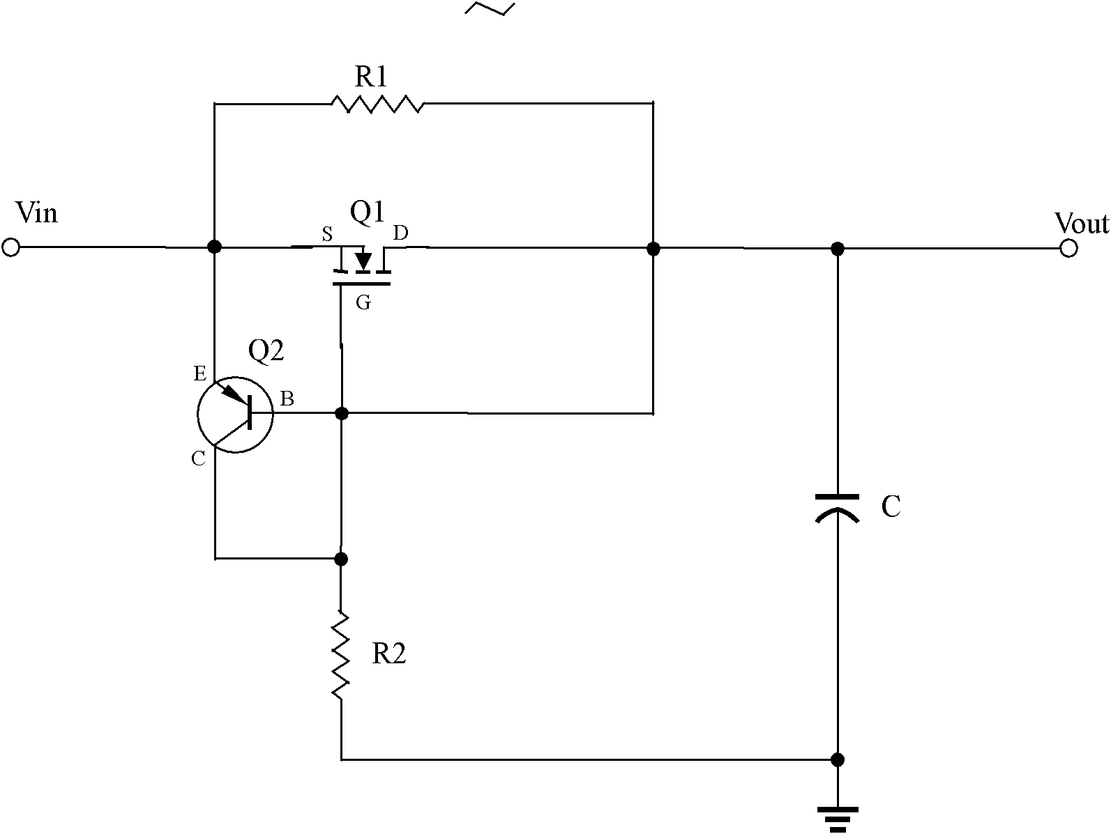
[0029] Such as figure 2 As shown, different from what is introduced in the background technology, please refer to the background technology Picture 1-1 , the base of the transistor Q2 is not directly connected to the collector of the transistor Q2, but connected to the drain of the MOS transistor Q1 through the resistor R2, and the drain of the MOS transistor Q1 is not directly connected to the source of the MOS transistor Q1; the transistor Q2 is NPN type transistor, MOS transistor Q1 is an N-channel power type MOS transistor, if the capacitor is a polarized capacitor such as an electrolytic capacitor, it can be connected according to the actual polarity when connecting. Specific connection relationship: including voltage input terminal Vin-, voltage output terminal Vout-, MOS transistor Q1, triode Q2, capacitor C, first resistor R1, second resistor R2, third resistor R3, voltage input terminal Vin- respectively connected to MOS The source of the transistor Q1 is connected ...

Embodiment 2

[0039] Such as image 3 As shown, the difference from Embodiment 1 is that the triode Q2 is a PNP transistor, and the MOS transistor Q1 is a P-channel power MOS transistor, and the connection relationship remains unchanged. If the capacitor uses a polarized capacitor such as an electrolytic capacitor, when connected Connect it correctly according to the actual polarity, and change the external power supply to a positive power supply.

[0040] Its working principle is the same as that described in Embodiment 1, and will not be repeated here. Embodiment 2 is suitable for a circuit with positive power input.

Embodiment 3

[0042] The principle of the third embodiment is completely the same as that of the first embodiment, as Figure 4 As shown, only the connection relationship with the external power supply is changed, the power input terminal of the first embodiment is changed to the ground wire of the external power supply, and the ground wire of the first embodiment is changed to the positive input of the external power supply; the ground wire of the first embodiment is output It is changed to output voltage positive, and the output port of Embodiment 1 is changed to an output ground wire; the output ground wire and the external power supply ground wire are two different networks. Embodiment 3 can also achieve surge suppression; the working principle of the circuit in Embodiment 3 is the same as that described in Embodiment 1, and will not be repeated here.

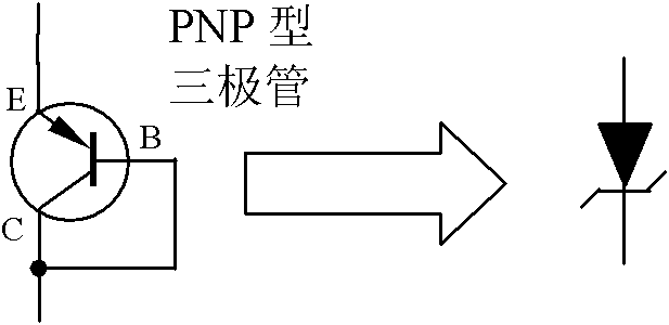
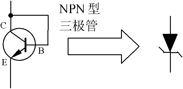
[0043] In addition, triodes or known composite tubes or IGBT tubes can also be used to replace the MOS tubes, such as NPN type triodes ...


PUM


Abstract

The invention discloses a surge suppression circuit which comprises a voltage input end, a voltage output end, a field-effect tube, a transistor, a capacitor, a first resistor, a second resistor and a third resistor, wherein the voltage input end is connected with the source electrode of the field-effect tube and the emitting electrode of the transistor respectively; the voltage input end is also connected with the drain electrode of the field-effect tube through the first resistor; the collector electrode of the field-effect tube is grounded through the third resistor; the base electrode of the transistor is connected with the drain electrode of the field-effect tube through the second resistor; and the drain electrode of the field-effect tube is grounded through the capacitor and also connected with the voltage output end. The surge suppression circuit suppresses surge voltage effectively; after the circuit is in a steady state, the power consumption of the surge suppression circuit is reduced; the surge suppression circuit has the function of load short circuit protection; and when an external power supply generates surge voltage, the surge suppression circuit offers dynamic and real-time protection.

Description

technical field [0001] The invention relates to a power supply protection circuit, in particular to surge suppression of a capacitance filter circuit. Background technique [0002] In the current various electrical appliances, there are a large number of rectification circuits, such as mains, after rectification, capacitor filtering, and then supply power to the conversion circuit of switching power supply; such as traditional power supply, after the mains is stepped down by a transformer, after rectification, capacitor filtering Then supply power to other circuits. When the power switch of this kind of electrical appliances is turned on, due to the existence of the filter capacitor, the voltage at both ends of the filter capacitor is instantly charged from 0V to the rated working voltage, which will generate a large surge voltage and surge current. The inrush current not only shortens the life of the filter capacitor, but also has a greater impact on the diodes, fuses, and ...

Claims


Application Information

Patent Timeline
Patent Type & Authority Applications(China)
IPC IPC(8): H02H9/04H02H9/02
Inventor 王保均
Owner MORNSUN GUANGZHOU SCI & TECH
Why Eureka
Try Eureka