Simple spot-welding robot mechanism

A robot and spot welding technology, which is applied in welding equipment, auxiliary welding equipment, welding/cutting auxiliary equipment, etc., can solve the problems of large moment of inertia of the robot structure, large cumulative error, and reduced rigidity of the robot, so as to achieve small cumulative work error, Low manufacturing cost and weight reduction effect

CN102091899AInactive Publication Date: 2011-06-15GUANGXI UNIV
4 Cites 11 Cited by

Patent Information

Authority / Receiving Office
CN · China
Patent Type
Applications(China)
Current Assignee / Owner
Publication Date
2011-06-15
Estimated Expiration
Not applicable · inactive patent

Smart Images

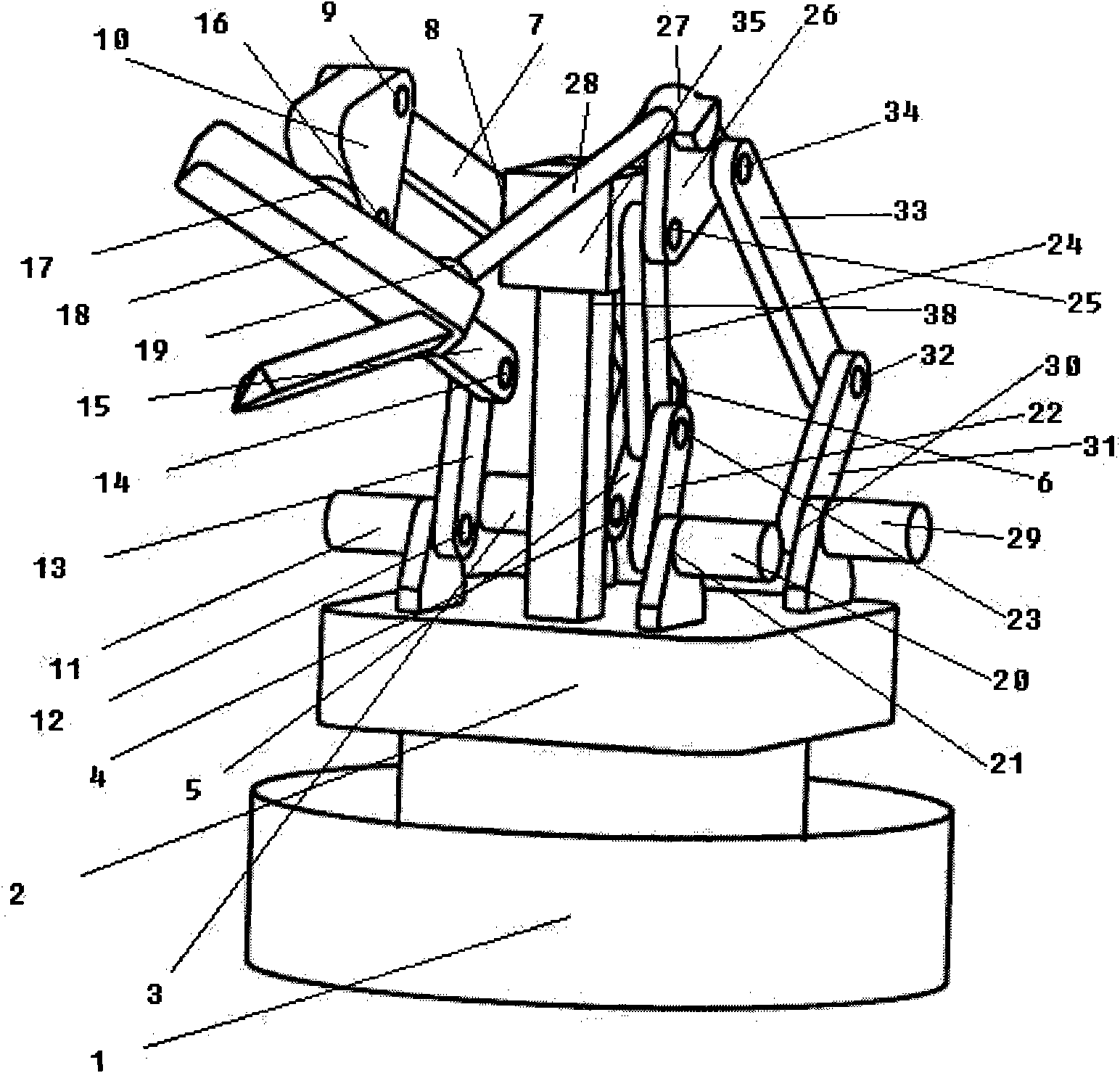
  • Figure 1
    Figure 1
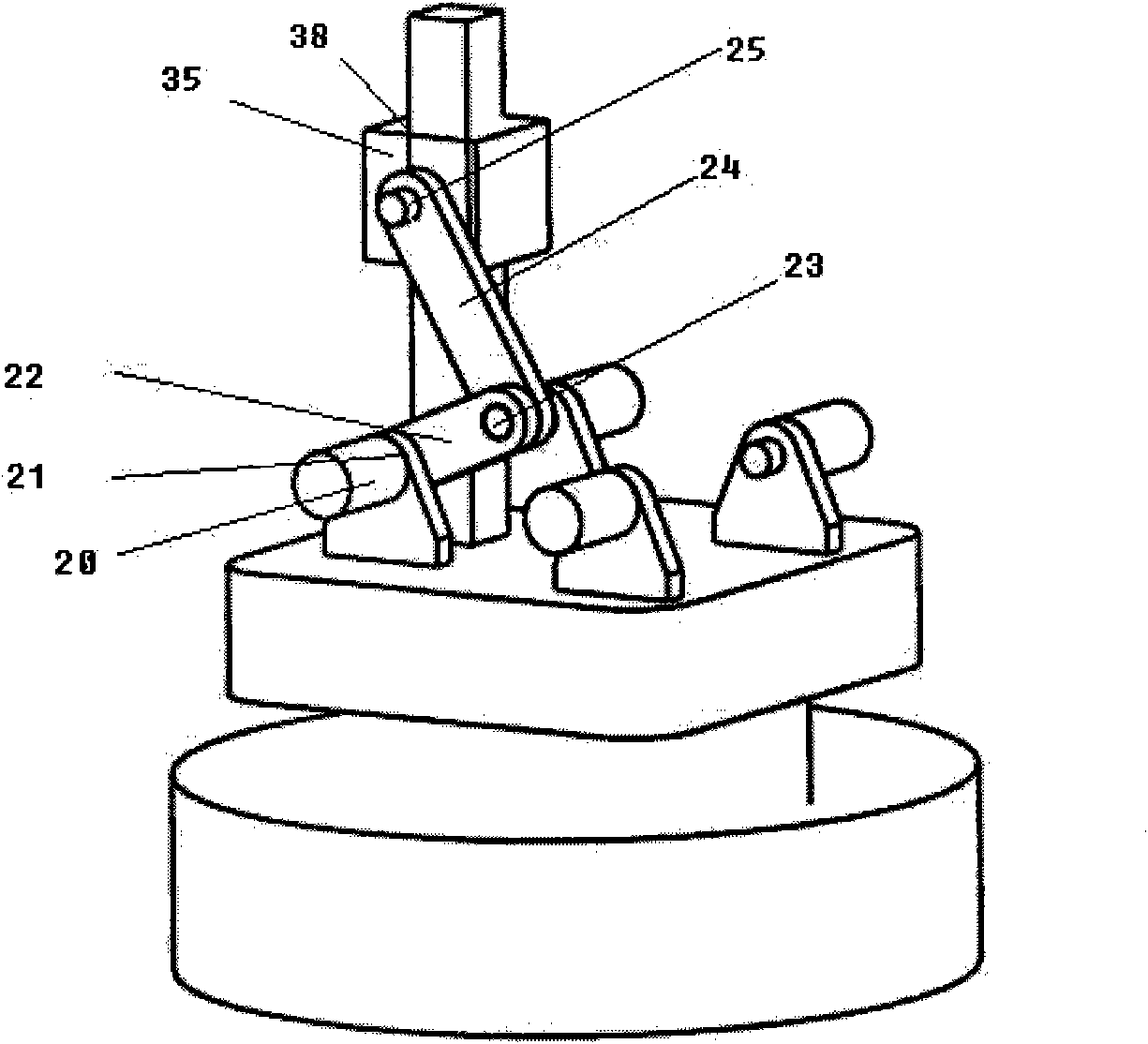
  • Figure 2
    Figure 2
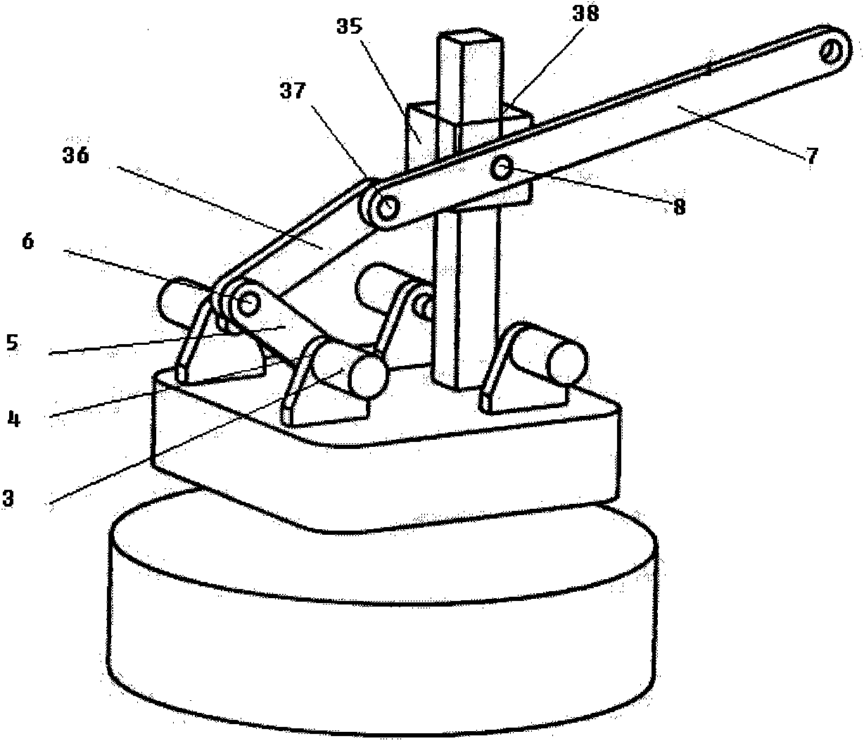
  • Figure 3
    Figure 3
Patent Text Reader

Abstract

The invention relates to a simple spot-welding robot mechanism which comprises a first welding torch rack position adjusting mechanism, a first welding torch rack attitude adjusting mechanism, a second welding torch rack position adjusting mechanism, a second welding torch rack attitude adjusting mechanism, a welding torch rack and a stand, wherein the welding torch rack is composed of a swinging rack and a rotating rack, the swinging rack is connected with the rotating rack by a fourteenth rotating pair, the swinging rack is connected with the first welding torch rack position adjusting mechanism by a fifteenth rotating pair, the swinging rack is connected with the first welding torch rack attitude adjusting mechanism by a tenth rotating pair, the rotating rack is connected with the second welding torch rack attitude adjusting mechanism by a second spherical pair, and a welding torch is arranged on the rotating rack. The simple spot-welding robot mechanism provided by the invention is driven by external rotating pairs, and all servo motors are installed on the stand, therefore, the weight of working bar parts can be reduced effectively, the accurate positioning of the working bar parts can be realized, and the working efficiency of the working bar parts can be improved.
Need to check novelty before this filing date? Find Prior Art

Description

technical field

[0001] The invention relates to the field of industrial welding robots, in particular to a simple spot welding robot mechanism. Background technique

[0002] Welding robots are industrial robots that are engaged in welding, including cutting and spraying. According to the definition of the International Organization for Standardization (ISO) Industrial Robot Terminology Standard, an industrial robot is a multi-purpose, reprogrammable automatic control manipulator (Manipulator), with three or more programmable axes, used in industrial automation field. Spot welding is not very demanding on the robot used. Because spot welding only needs point control, there is no strict requirement for the movement trajectory of the welding tongs between points. The welding robots produced in various countries in the world are basically articulated robots, and most of them have 6 axes. Among them, the 1, 2, and 3 axes can send the end tool to different spatial positions, wh...

Examples

Embodiment Construction

[0023] The technical solutions of the present invention will be further described below with reference to the accompanying drawings and embodiments.

[0024] control figure 1 , 2 , 3, 4 and 5, a simple spot welding robot mechanism, including a first welding gun frame position adjustment mechanism, a second welding gun frame position adjustment mechanism, a first welding gun frame attitude adjustment mechanism, a second welding gun frame attitude adjustment mechanism, a welding gun frame and rack 2. The frame 2 can be installed on the rotary platform 1 to realize the motion of the entire robot space with five degrees of freedom.

[0025] control figure 1 , 2 , the first welding gun frame position adjustment mechanism is connected by the first servo motor 3, the first active rod 5, the first connecting rod 36, the second connecting rod 7, the slider 35, the swing frame 10 and the frame 2, One end of the first active rod 5 is connected with the first servo motor 3 through th...