Cable diagnosis system, method and system for configuring Ethernet port
A diagnostic system, Ethernet technology, applied in transmission systems, digital transmission systems, electrical components, etc., can solve problems such as time consumption and money
Inactive Publication Date: 2011-06-15
AVAGO TECH WIRELESS IP SINGAPORE PTE
View PDF3 Cites 4 Cited by
- Summary
- Abstract
- Description
- Claims
- Application Information
AI Technical Summary
Problems solved by technology
This process takes time and a lot of money
Method used
View moreImage
Smart ImageViewing Examples

Examples
Embodiment Construction
Login to View More PUM
 Abstract
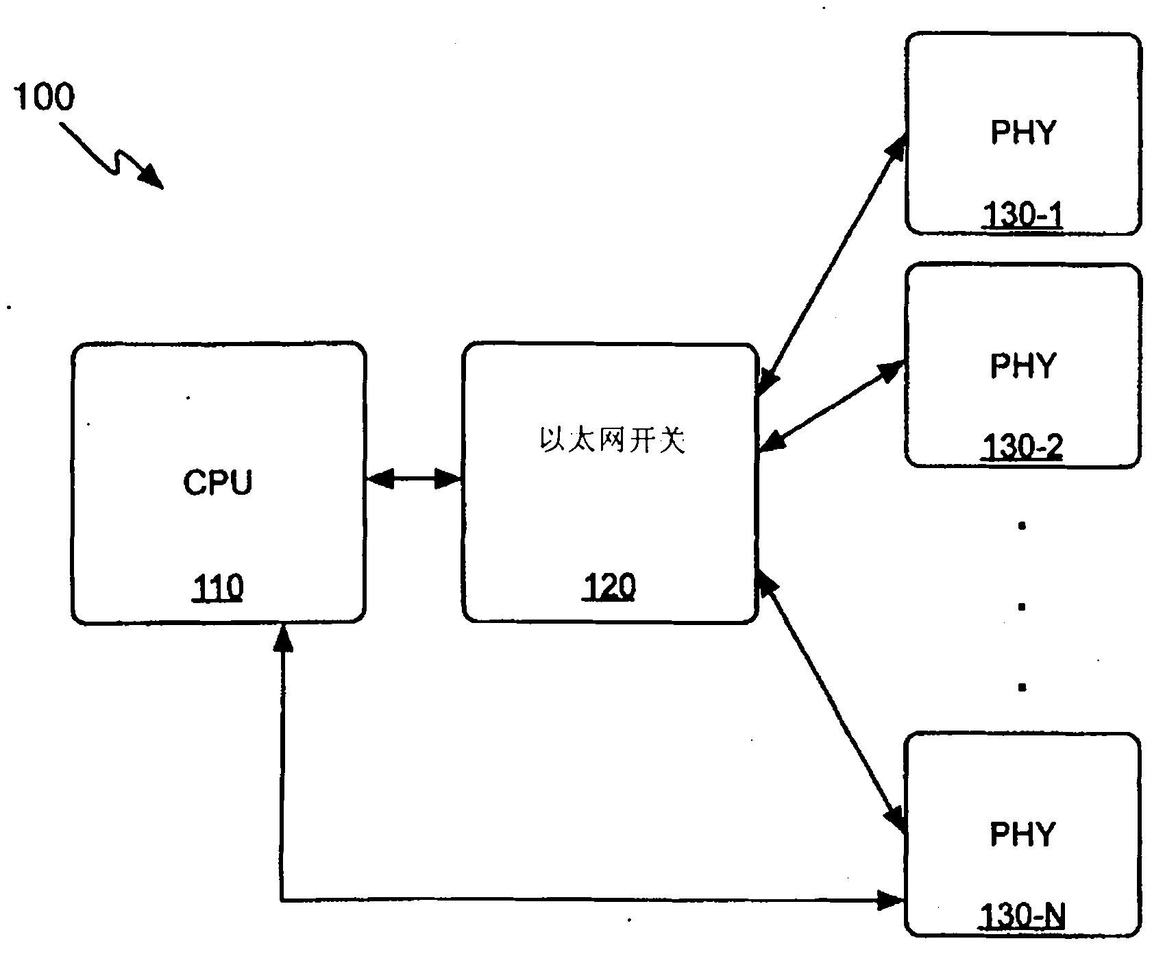
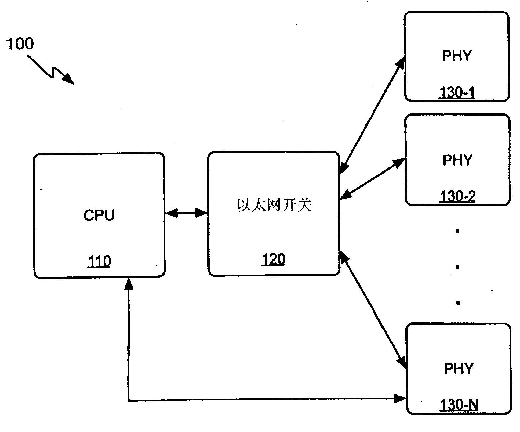
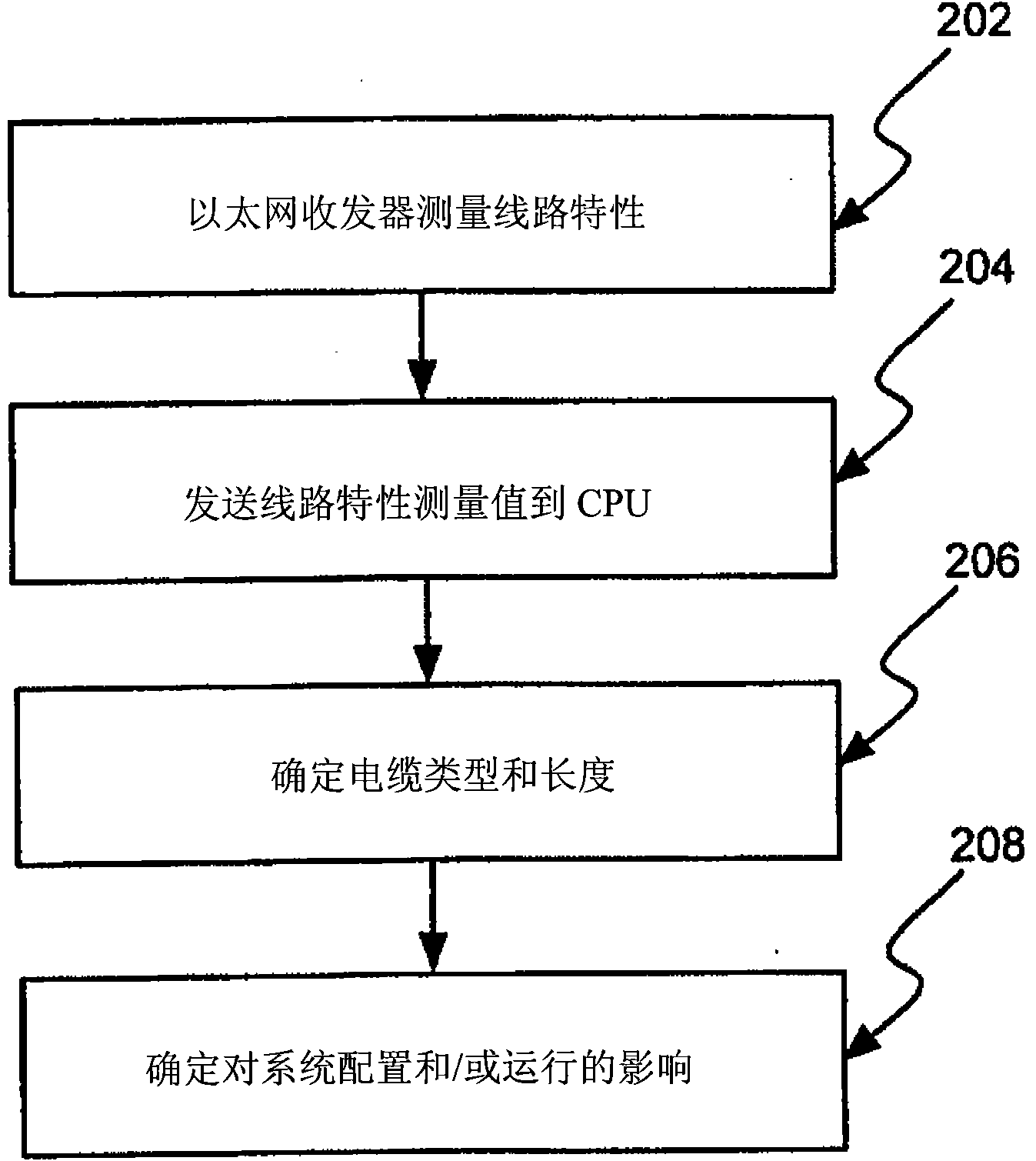
The invention relates to a cable diagnosis system, method and system for configuring Ethernet port, more concretely a system and method for discovering a cable type using an automated, systematic process. A PHY can be designed to measure electrical characteristics (e.g., insertion loss, cross talk, length, etc.) of the cable to enable determination of the cable type. The determined cable type can be used in diagnosis of cabling infrastructure or in a dynamic configuration or operation process.
Description
Cable diagnostic system and method and system for Ethernet port configuration This application is a divisional application of a Chinese invention application with an application date of December 14, 2007, an application number of 200710160257.3, and an invention titled "Cable Diagnostic System and Ethernet Port Configuration Method and System". technical field The present invention relates to systems and methods for network cabling, and more particularly, to diagnostics of cabling infrastructure. Background technique The development of computer networks has contributed to an increase in the use of network cables. Initially, 10BASE-T Ethernet may be supported using Category 3 cabling with "telephone grade" cabling. These inexpensive twisted pair cables support distances up to 100 meters. As network speeds increase, Category 3 cables can no longer support higher transmission speeds. Therefore, Category 5 cables are used to support Fast Ethernet such as 100BASE-T. Today...
Claims
Login to View More Application Information
Patent Timeline
 IPC IPC(8): H04L12/24H04L12/10
CPCH04L41/12H04L41/0806H04L12/4625
Inventor 韦尔·威廉·戴博明夏因·希赫
Owner AVAGO TECH WIRELESS IP SINGAPORE PTE

PatSnap Eureka turns technology decisions into work you can execute. Powered by our Innovation Knowledge Graph, it runs expert workflows across engineering, life sciences, materials and intellectual property. Get your review-ready output in minutes.


