Photovoltaic grid-connected inverter and control method

An inverter, photovoltaic technology, applied in photovoltaic power generation, irreversible DC power input conversion to AC power output, single-grid parallel feeding arrangement, etc., can solve the problem of unstable operation, low output voltage level of photovoltaic system, increased System cost and other issues, to achieve the effect of improving system power level, improving grid-connected power quality, and improving system stability

Active Publication Date: 2013-09-18
GUANGZHOU ZHIGUANG ELECTRIC CO LTD +1
View PDF6 Cites 0 Cited by
  • Summary
  • Abstract
  • Description
  • Claims
  • Application Information

AI Technical Summary

Problems solved by technology

[0004] Because the output power of the photovoltaic system depends on the lighting conditions, and the lighting is uncertain, the grid-connected power fluctuates greatly, especially when the lighting is suddenly blocked, the system has to go off-grid and stand by, and the operation is unstable; a switch tube in the system Partial failures such as battery panels and other local faults often lead to downtime, and the safety of the system is low; the output voltage level of the photovoltaic system is low, and the grid connection generally needs to be boosted by a transformer, which increases the cost of the system; limited to the load capacity of current power electronic devices , it is difficult to further increase the power level of photovoltaic grid-connected inverters, especially to achieve the level of a single megawatt; moreover, as the power level increases, the operating frequency of the switching tube will inevitably decrease, which will lead to current harmonics wave problem

Method used


Image

  • Photovoltaic grid-connected inverter and control method
  • Photovoltaic grid-connected inverter and control method
  • Photovoltaic grid-connected inverter and control method

Examples


Embodiment 1

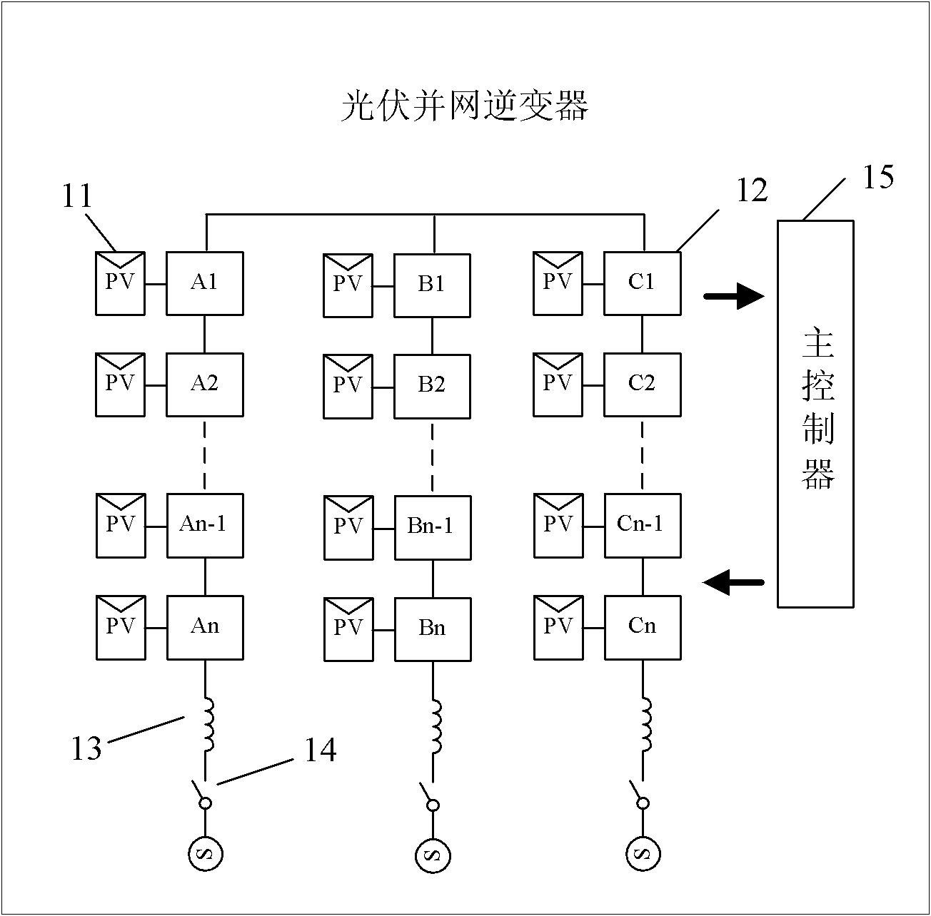
[0050] see figure 1 , is a structural diagram of a photovoltaic grid-connected inverter according to an embodiment of the present invention. As shown in the figure, the inverter includes a plurality of photovoltaic arrays 11, a plurality of unit cells 12, three AC reactors 13, and three grid-connected switch 14 and a master controller 15.

[0051] Each phase of the inverter is composed of multiple units 12 cascaded through the unit phase-shifting stacking wave technology. The unit units A1, A2...An-1, An in the figure form phase a of the inverter, B1, B2...Bn-1, Bn, etc. constitute phase b of the inverter, and C1, C2...Cn-1, Cn, etc. constitute phase c of the inverter. Unit cascading means that each unit is connected end-to-end to achieve high-voltage output. Using unit cascading or series technology, higher-level voltages can be output, such as direct output voltages of 3kV, 6kV, 10kV, or even higher-level voltages. Wherein, the input end of each unit cell 12 in the branch ...

Embodiment 2

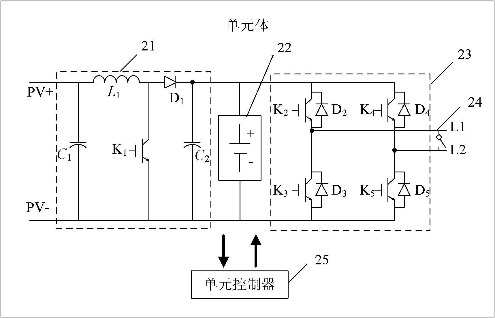
[0056] figure 2 It is the circuit principle diagram of the unit body of the embodiment of the present invention. As shown in the figure, the unit body includes:

[0057] The BOOST circuit 21 is used for performing maximum power tracking on the photovoltaic array, and raising the low voltage output by the photovoltaic array to a high voltage;

[0058] The energy storage battery 22 is used to store the electric energy provided by the BOOST circuit 21, and to provide stable DC power to the rear-stage H-bridge inverter circuit 23; due to the effect of the energy storage battery 22, when the light suddenly disappears, the inverter system does not It will suddenly go offline and stand by, which improves the stability of the system;

[0059] The H-bridge inverter circuit 23 is used to invert the direct current provided by the energy storage battery 22 into alternating current by using carrier phase-shifting SPWM technology;

[0060] The bypass switch 24 is used to perform bypass ...

Embodiment 3

[0064] The unit controller 25 and the main controller 15 will be introduced in detail below, and the control method of the grid-connected inverter will be described in detail.

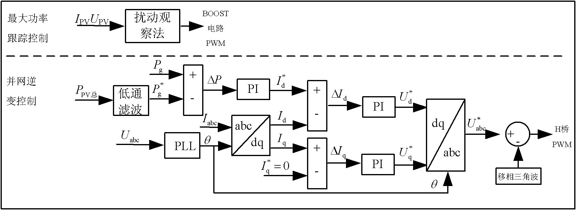
[0065] Unit controller 25, with digital signal processor (DSP) and programmable logic device (CPLD) as the core, monitors each unit, and feeds back unit failure, temperature, photovoltaic array terminal voltage and output current and other parameter information, and perform maximum power tracking control on the photovoltaic array; the above-mentioned maximum power tracking control on the photovoltaic array is specifically based on the terminal voltage U of each photovoltaic array sampled in real time PVk and output current I PVk , to calculate the output power P PVk (k=a 1 ,...,a n ;b 1 ,...,b n ; c 1 ,...,c n ), using the perturbation and observation method to perform maximum power tracking control on the photovoltaic array, so that the photovoltaic array works at the maximum power point, and s...


PUM


Abstract

The invention discloses a photovoltaic grid-connected inverter. The photovoltaic grid-connected inverter comprises a photovoltaic array, a plurality of unit bodies, three unit body series branches, an alternating current reactor, a grid-connected switch, unit body controllers and a master controller, wherein the preceding stage of each unit body is respectively connected with the photovoltaic array; the unit body series branches are connected into a power grid after being connected with the alternating current reactor and the grid-connected switch in series; and each unit body comprises one of the unit body controllers. The invention also discloses a photovoltaic grid-connected inverter control method. In the inverter and the control method disclosed by the invention, the unit bodies are connected in series instead of directly connecting power devices in series, so that the problem of voltage-sharing of devices are solved; the power level is high; the limitation of load capacity of power electronic devices is overcome; a unit phase shift wave overlapping technology is adopted, so that an output harmonic wave is small; because of the action of an energy storage battery, when illumination disappears suddenly, a system cannot be off-grid and standby suddenly; and because of adopting a unit body automatic bypass technology, the security of the system is improved.

Description

technical field [0001] The invention relates to the technical field of photovoltaic power generation, in particular to a photovoltaic grid-connected inverter and a control method. Background technique [0002] Solar energy is one of the most dynamic new energy sources in the 21st century. Photovoltaic power generation is developing from small-scale off-grid power generation to large-scale grid-connected power generation. The capacity of photovoltaic grid-connected power generation systems is increasing, and megawatt-level systems are the direction of future development. Therefore, it is of great significance to study high-power high-voltage photovoltaic grid-connected inverters and their control methods. [0003] Photovoltaic grid-connected inverters based on various topologies and control methods have been widely studied, but it is still difficult to meet the requirements of stability, safety, economy and high power quality, as follows: [0004] Because the output power o...

Claims


Application Information

Patent Timeline
Patent Type & Authority Patents(China)
IPC IPC(8): H02M7/42H02M7/537H02J3/38
CPCY02E10/563Y02E10/56
Inventor 许贤昶邱培春孙开发刘润予
Owner GUANGZHOU ZHIGUANG ELECTRIC CO LTD
Why Eureka
Try Eureka