
Positioning device for moveable step ladder

A positioning device and the technology of climbing ladders, which are applied in the field of climbing ladders, can solve problems such as hidden safety hazards, inconvenient use, and inconvenient handling, and achieve the effects of ensuring safety, high stability, and convenient movement

Inactive Publication Date: 2011-07-06
SHANGHAI POWERWAY LOGISTICS EQUIP
View PDF0 Cites 5 Cited by
  • Summary
  • Abstract
  • Description
  • Claims
  • Application Information

AI Technical Summary

Problems solved by technology

[0003] At present, the following methods are used for climbing operations: 1) the traditional two-legged ladder is used for climbing operations. Because the traditional two-legged ladder is very easy to slip, there is a great potential safety hazard in this operation method, and this Ladders also have high requirements for the space on the job site, and it is very inconvenient to use; 2) Use ordinary herringbone-shaped climbing ladders for climbing operations. Convenience; 3) Use a herringbone-shaped climbing ladder with a moving device at the bottom for climbing operations. This climbing ladder is usually composed of universal wheels and a brake mechanism. After the brake mechanism is released, it can be easily moved through the universal wheels to After specifying the position, the brake mechanism can be used to lock the universal wheel; however, under heavy load conditions, it often happens that the brake mechanism cannot lock the universal wheel, so its stability cannot be guaranteed even under heavy load conditions. Affect workers' safety at work

Method used


Image

  • Positioning device for moveable step ladder
  • Positioning device for moveable step ladder
  • Positioning device for moveable step ladder

Examples


Embodiment Construction

[0013] The embodiments of the present invention will be described in further detail below in conjunction with the accompanying drawings, but the present embodiments are not intended to limit the present invention, and any similar structures and similar changes of the present invention should be included in the protection scope of the present invention.

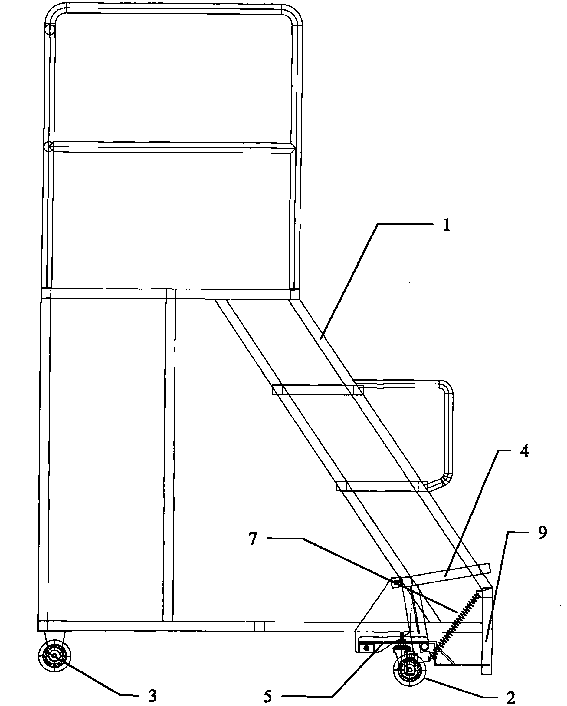
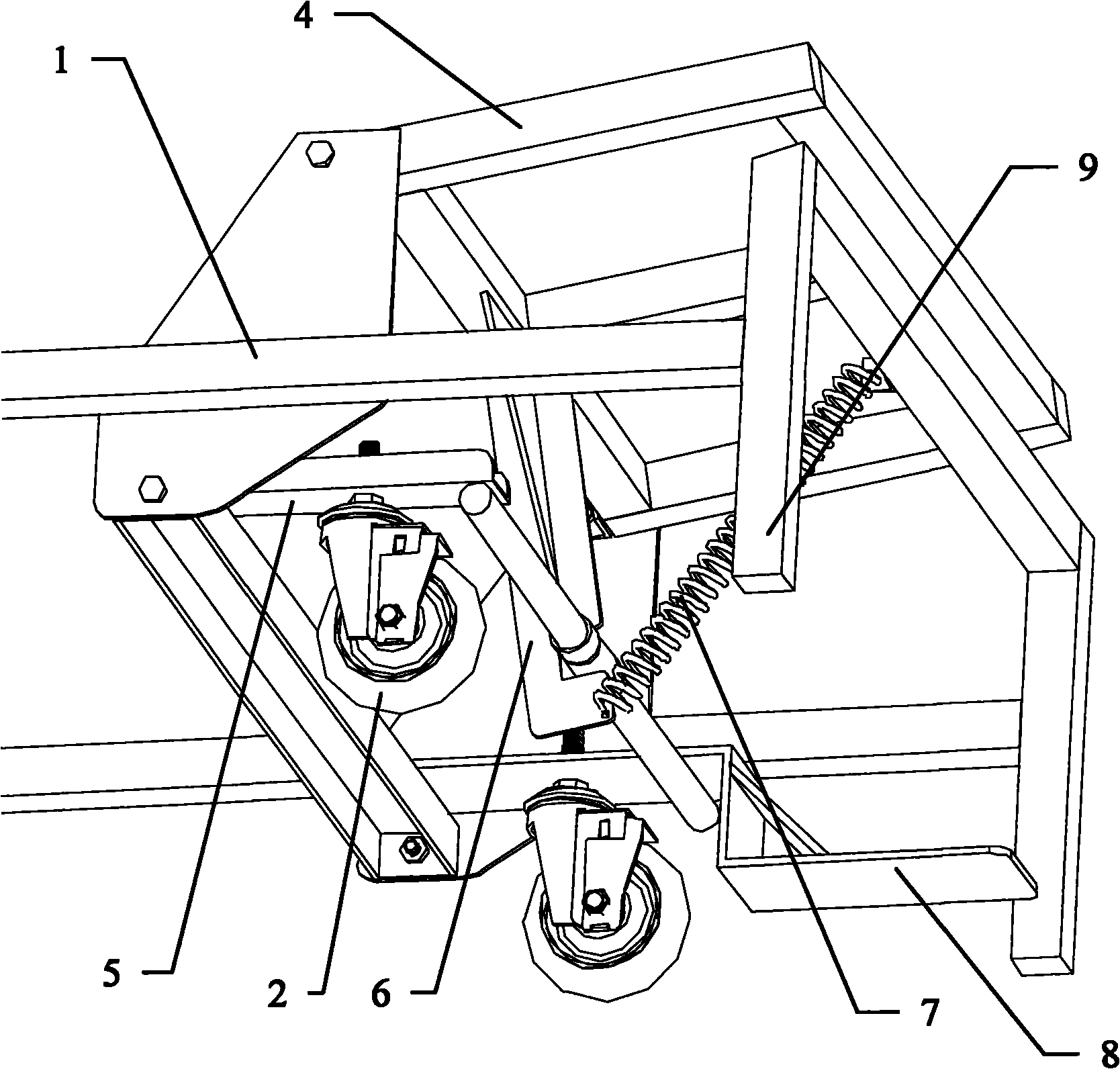
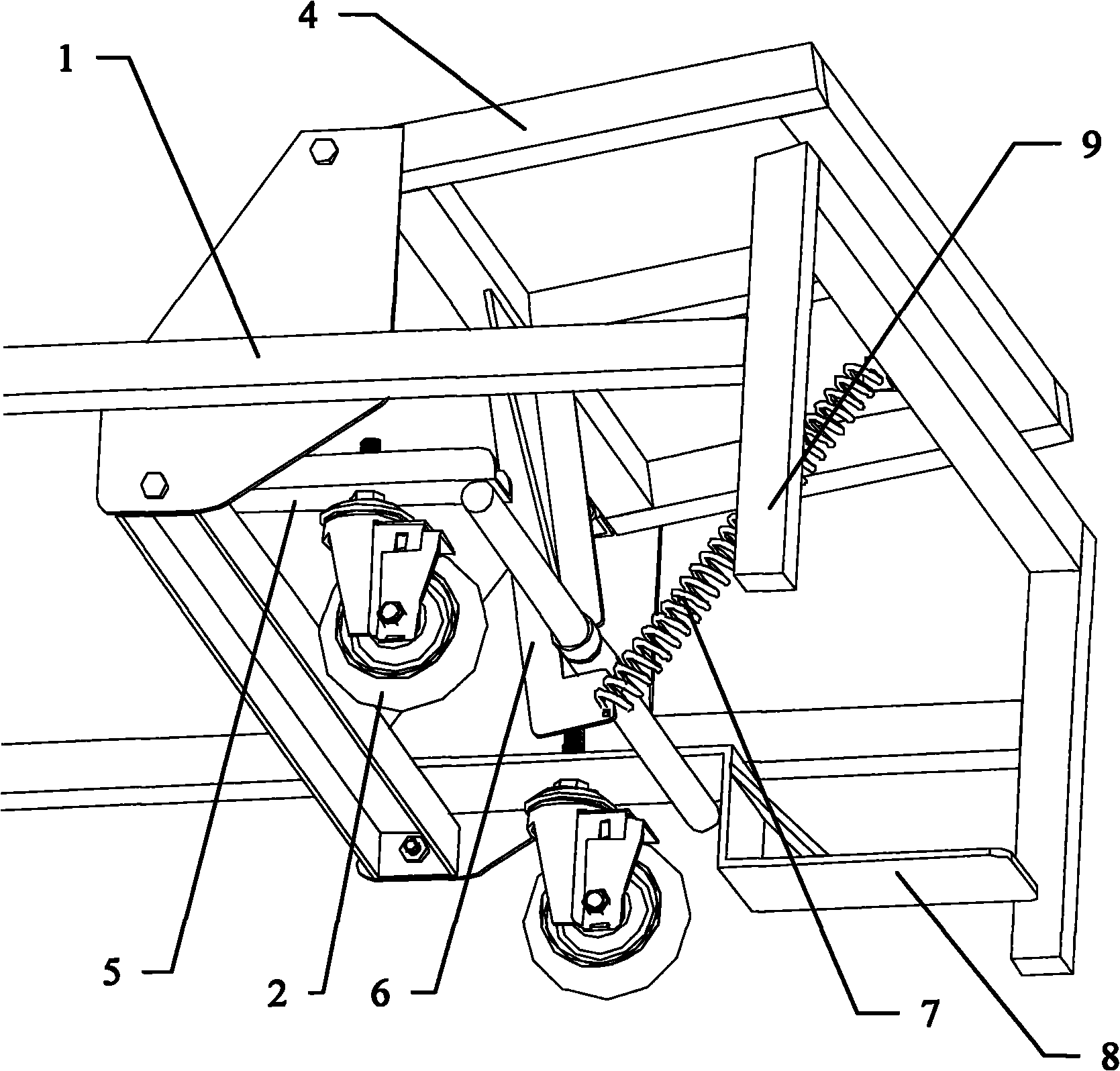
[0014] Such as Figure 1-Figure 2 As shown, a mobile climbing ladder with a positioning device provided by the embodiment of the present invention includes a ladder frame 1, two front wheels 2 and two rear wheels 3, and is characterized in that it also includes a positioning pedal 4, a Rectangular movable frame 5, a lock bar 6, a spring 7, a positioning release plate 8;

[0015] The rear frame limit of described rectangular movable frame 5 is pivotally connected with the lower end of ladder frame 1, and its pivot axis is parallel to the ground, and the two rear wheels 3 are installed on the two side frame edges of rectangular ...


PUM


Abstract

The invention provides a positioning device for a moveable step ladder, relating to the technical field of step ladders and aiming at solving the technical problem of poor stability of the existing step ladder. The step ladder comprises a ladder frame, two front wheels, two rear wheels, a positioning footboard, a rectangular moveable frame, a lock rod, a spring and a depositioning board, wherein the rear frame edge of the rectangular moveable frame is connected with the lower end of the ladder frame in a pivoting manner, and the two rear wheels are respectively installed on the edges of both sides of the rectangular moveable frame; the bottom of the front end of the ladder frame is provided with two bottom feet; the rear side edge of the positioning footboard is connected with the lower end of the ladder frame in a pivoting manner, the upper end of the lock rod is fixedly connected with the rear end of the positioning footboard, and the lower end of the lock rod is caused to downwards penetrate through the surface of the rectangular moveable frame; one end of the spring is fixedly connected with the lower end of the lock rod, and the other end of the spring is fixed at the front end of the ladder frame; the lower part of the lock rod is provided with a bayonet; and one end of the depositioning board is fixedly connected with the rectangular moveable frame, and the other end is caused to forwards extend out of the frame body. The step ladder can be conveniently moved and positioned.

Description

technical field [0001] The invention relates to the technology of climbing ladders, in particular to the technology of a positioning device for moving climbing ladders. Background technique [0002] In the daily production and operation of enterprises, it is often necessary to perform height-climbing operations; for example, in the production workshop, there will be some positions higher than the ground that require workers to perform height-elevation operations, and in the warehouse, workers are required to ascend some of the materials stored in higher positions access. [0003] At present, the following methods are used for climbing operations: 1) the traditional two-legged ladder is used for climbing operations. Because the traditional two-legged ladder is very easy to slip, there is a great potential safety hazard in this operation method, and this Ladders also have high requirements for the space on the job site, and it is very inconvenient to use; 2) Use ordinary herr...

Claims


Application Information

Patent Timeline
Patent Type & Authority Applications(China)
IPC IPC(8): E06C1/397E06C7/42E06C7/00
Inventor 骆靓
Owner SHANGHAI POWERWAY LOGISTICS EQUIP
Learn More