Anti-drop electronic connector for data transmission
A technology for data transmission and electrical connectors, which is applied in the direction of connection, parts of connecting devices, and devices for reducing the stress at the connection of wires, etc. It can solve the problems of shortening the service life of electrical connectors, loose or disconnected connections, and poor connection stability. , to avoid the failure of signal transmission, easy assembly and long service life
- Summary
- Abstract
- Description
- Claims
- Application Information
AI Technical Summary
Problems solved by technology
Method used
Image

Examples
Embodiment 1
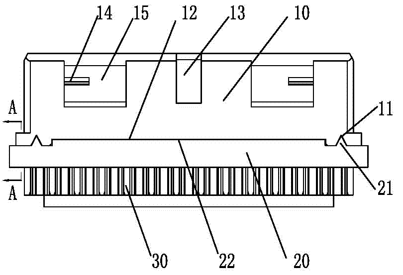
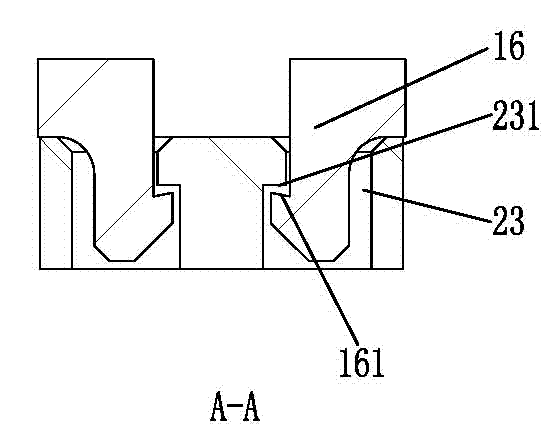
[0020] One of the specific implementations of an anti-falling data transmission electrical connector of the present invention, such as figure 1 and figure 2 As shown, it includes an insulating body 10, a rubber core 20 and a conductive terminal 30. The insulating body 10 is plugged and matched with the rubber core 20. The rubber core 20 is formed with a wire groove. The terminal 30 passes through the wire slot and is embedded in the penetration hole, wherein the four corners of the end face where the insulating body 10 and the rubber core 20 are plugged and mated are respectively provided with hooks 16 , and the rubber core 20 is provided with hooks 16 corresponding to the four corners. Corresponding to the clamping hole 23, the clamping hook 16 is closely matched with the clamping hole 23, and the edge of the end face where the rubber core 20 and the insulating body 10 are plugged and mated is respectively provided with a rectangular convex edge 22 and a triangular convex ed...
Embodiment 2
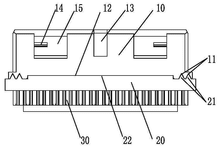
[0028] The second embodiment of an anti-falling data transmission electrical connector of the present invention is as follows: image 3 As shown, the main technical solution of this embodiment is the same as that of Embodiment 1, and the features not explained in this embodiment adopt the explanation in Embodiment 1, and will not be repeated here, and are described in image 3 neutralize figure 1 , figure 2 The same parts bear the same reference numerals. The difference between this embodiment and Embodiment 1 is that the rectangular flange 22 is arranged in the middle of the edge of the end face where the rubber core 20 is mated with the insulating body 10, and two triangular flanges are respectively provided on both sides of the rectangular flange 22. Side 21. Correspondingly, the insulating body 10 is provided with a rectangular groove 12 at a position corresponding to the rectangular protrusion 22 , and a triangular groove 11 is disposed at a position corresponding to ...
PUM
 Abstract
Description
Claims
Application Information
 - R&D
- Intellectual Property
- Life Sciences
- Materials
- Tech Scout
- Unparalleled Data Quality
- Higher Quality Content
- 60% Fewer Hallucinations
Browse by: Latest US Patents, China's latest patents, Technical Efficacy Thesaurus, Application Domain, Technology Topic, Popular Technical Reports.
© 2025 PatSnap. All rights reserved.Legal|Privacy policy|Modern Slavery Act Transparency Statement|Sitemap|About US| Contact US: help@patsnap.com