
In situ regolith gas recovery system

A regolith and gas technology, applied in solar heating systems, power supply systems for space vehicles, extraterrestrial vehicles, etc., can solve problems such as unpracticality of the system

Inactive Publication Date: 2011-07-13
ROCKETDYNE
View PDF5 Cites 0 Cited by
  • Summary
  • Abstract
  • Description
  • Claims
  • Application Information

AI Technical Summary

Problems solved by technology

However, the systems proposed so far are not practical

Method used


Image

  • In situ regolith gas recovery system
  • In situ regolith gas recovery system
  • In situ regolith gas recovery system

Examples


Embodiment Construction

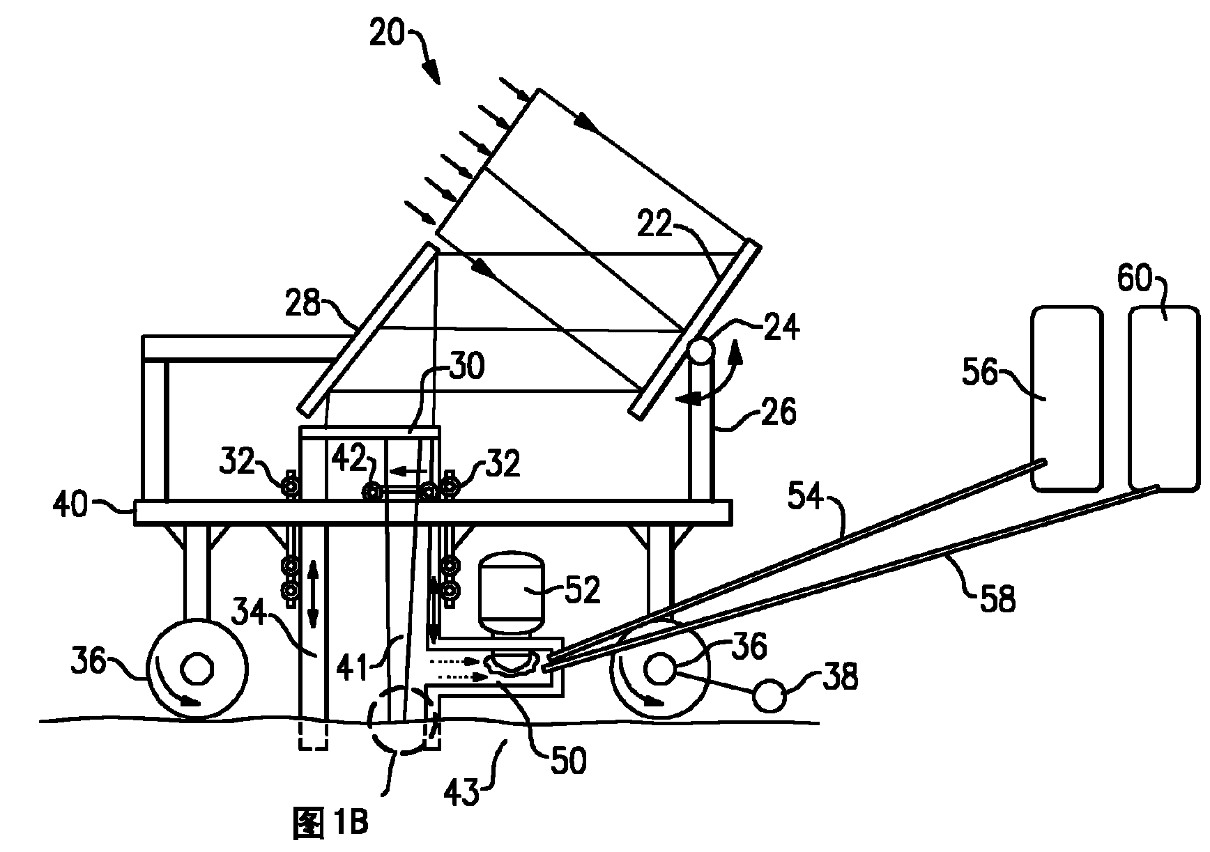
[0014] Figure 1A A system 20 is shown for recovering gas from regolith material 43 such as can be found in the first few meters of the surface of the moon and other space bodies. As shown, the system 20 includes a solar harvesting mirror 22 driven by a motor 24 (shown schematically) mounted atop a support 26 and operable to optimally position the sun's rays (or radiation) and Directed towards another rotating mirror 28 driven by its own motor. The controls for proper alignment of the two mirrors can be as known.

[0015] Focusing lens 30 is mounted on top of movable frame 34 . The movable frame 34 is movable by a motor and guide 32 to translate vertically upward relative to the housing 40 of the system 20 . The wheels 36 are provided with motors 38 (shown schematically) and are operable to move the entire system along the surface.

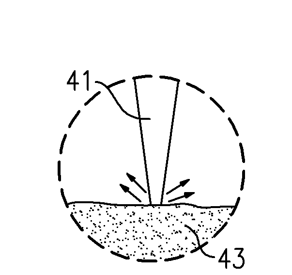
[0016] Lens 30 produces light rays 41 that direct high intensity solar energy onto the outer surface of regolith 43 .

[0017] Lunar regolith...


PUM


Abstract

The invention relates to an in situ regolith gas recovery system. A system for releasing and capturing gases from a regolith material has a frame that is movable to define a capture space on a regolith material. A mirror captures solar energy, and focuses energy through a lens and on a regolith defined within the captured space. Apparatus is provided for capturing released gas. A method of operating such a system is also disclosed and claimed. In addition, a method of forming structural material is also disclosed and claimed.

Description

technical field [0001] This application relates to a transport vehicle that is movable on a surface such as the moon's surface to bring a gas recovery system over a regolith area, then release the gas using solar energy, and recover the gas. Background technique [0002] The fields of space travel, colonization, and building space stations present several logistical challenges. One of the challenges of implementing a space station on the Moon or other non-Earth body is the need to transport all the required gas, supplies, etc. [0003] For example, transporting all the required gases to a lunar station would require a large amount of storage space on a vehicle traveling to the moon. [0004] On the other hand, it is known that the surface of the Moon, especially its regolith or loose rock and dust on the surface, comprises large quantities of recoverable gases. [0005] It has been proposed to release, capture and utilize these gases using solar energy. However, the syste...

Claims


Application Information

Patent Timeline
Patent Type & Authority Applications(China)
IPC IPC(8): B01D7/00B01D5/00F24S20/30F24S23/00
CPCY02E10/44B64G1/16B64G1/44Y02E10/47Y10T137/0318Y10T137/8593
Inventor A·J·齐尔默J·P·凯罗尔
Owner ROCKETDYNE
Learn More