Switch operating device

A technology of operating devices and switches, which is applied to the power device inside the switch, contact operating mechanism, electric switch, etc., can solve the problems of time-consuming, difficult assembly and adjustment, poor transmission efficiency, etc., and achieve easy three-position control Effect

Active Publication Date: 2011-07-20
KK TOSHIBA
View PDF9 Cites 14 Cited by
  • Summary
  • Abstract
  • Description
  • Claims
  • Application Information

AI Technical Summary

Problems solved by technology

In other words, conventional operating devices for switches that can perform three-position control and have different operating angles or operating amounts between circuit breakers and grounding switches have poor transmission efficiency, so the output and external shape of the motor are correspondingly large. , or the operating device for the switch is composed of a catcher and a catcher coil in such a way that the "cut-off" position can be held and released, and the structure is complicated
In addition, since the motor limit switch is provided separately for the "on" state and "off" state of the circuit breaker and the grounding switch, it is difficult to assemble and adjust the position of the limit switch relative to the cam. time consuming

Method used


Image

  • Switch operating device
  • Switch operating device
  • Switch operating device

Examples


Embodiment Construction

[0097] Next, an embodiment of an operating device for a switch according to the present invention will be described with reference to the drawings. Here, with Figure 8 The same or similar parts in the prior art shown are assigned the same reference numerals, and repeated explanations are omitted.

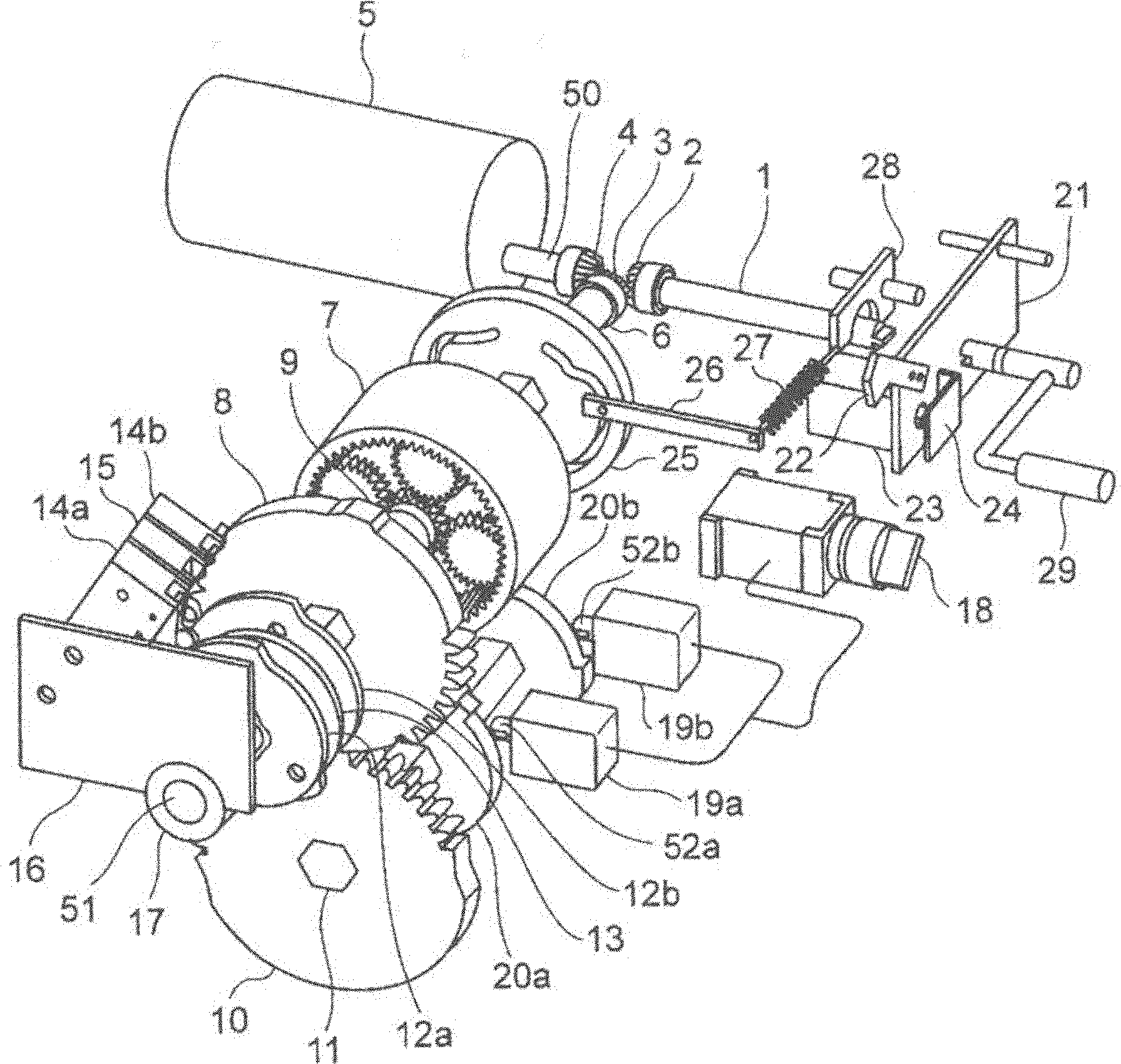
[0098] figure 1 It is a perspective view showing one embodiment of the operating device for a switch of the present invention.

[0099] The motor 5 has a motor output shaft 50, with reference to Figure 7 As will be described later, positive rotation and negative rotation can be performed by switching the electrical contacts. A bevel gear 4 is fixed on the motor output shaft 50 , and the bevel gear 4 meshes with the bevel gear 3 fixed on the drive shaft 6 .

[0100] The rotating shaft of the manual operation shaft 1 is arranged on the same straight line as the motor output shaft 50, but it is another independent shaft. The bevel gear 2 is fixed on the manual operation shaft 1, ...


PUM


Abstract

The present invention provides a switch operating device capable of easily achieving three-point control even in the case where the disconnector and grounding switch have different operating angle or operating amount. The switch operating device has: an electric motor (5) capable of being rotated in both positive and negative directions; a drive shaft (6) rotated by the electric motor (5); a drive-side intermittent gear (8) rotated by the drive shaft (6); a driven-side intermittent gear (10) rotated by the drive-side intermittent gear (8); a main shaft (11) that is fixed to the driven-side intermittent gear (10) to drive the contacts of the switch; a disconnector lock cam (19a) and a grounding switch lock cam (19b) fixed to the main shaft (11) to be rotated; and a disconnector lock pin (52a) and a grounding switch lock pin (52b) that are capable of being engaged with and released from the disconnector lock cam (19a) and the grounding switch lock cam (19b) and capable of inhibiting predetermined range of rotation of the main shaft (11) when being engaged.

Description

technical field [0001] The present invention relates to an operating device for a switch for operating a contact of a switch having a three-position structure having different operating angles or strokes between a circuit breaker and a grounding switch. Background technique [0002] Among gas insulated switchgears used in power transformation equipment, switchgears in which a main contact of a circuit breaker and a main contact of an earthing switch for work are shared and the size of the equipment is reduced are often used. The gas insulated switchgear uses one operating device to open and close two switches such as a circuit breaker and a grounding switch, and can switch on, "off" and "grounding" the three main contacts. An operating device for a three-position switch that controls the point position. [0003] On the other hand, according to the JEC2310-2003 standard of the Japan Electrical Society Electrical Standards Investigation Committee, the insulation performance b...

Claims


Application Information

Patent Timeline
Patent Type & Authority Applications(China)
IPC IPC(8): H01H3/26H01H3/40H01H3/42H01H9/26
CPCH01H31/003H01H3/40H01H3/3047H01H3/42
Inventor 冈成信明向田彰久
Owner KK TOSHIBA
Why Eureka
Try Eureka