Uplink dispatching method
A scheduling method and technology for user equipment, applied in the field of communication, can solve problems such as inability to determine data bearer, and achieve the effect of improving wireless performance and scheduling efficiency
- Summary
- Abstract
- Description
- Claims
- Application Information
AI Technical Summary
Problems solved by technology
Method used
Image
Examples
Embodiment 1
[0051] The UE has two DS grants, which come from the uplink grants of HARQ entity 1 and HARQ entity 2 corresponding to CC1 and CC2 respectively.
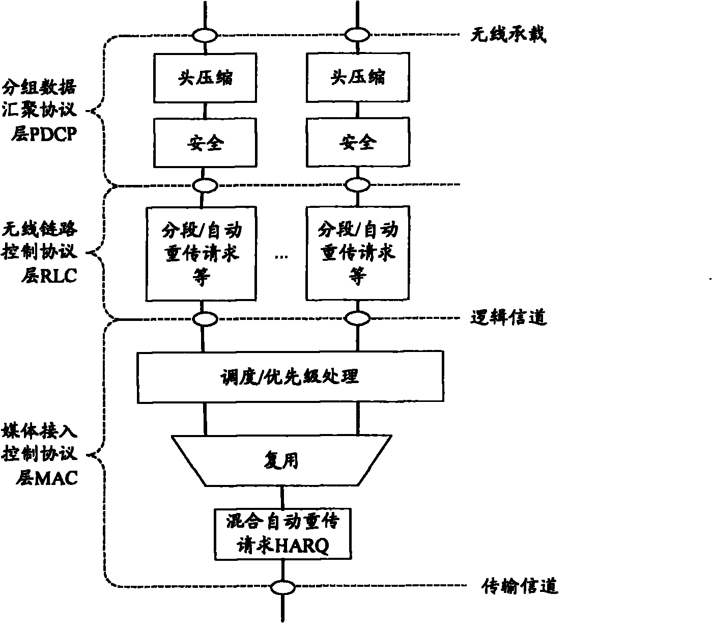
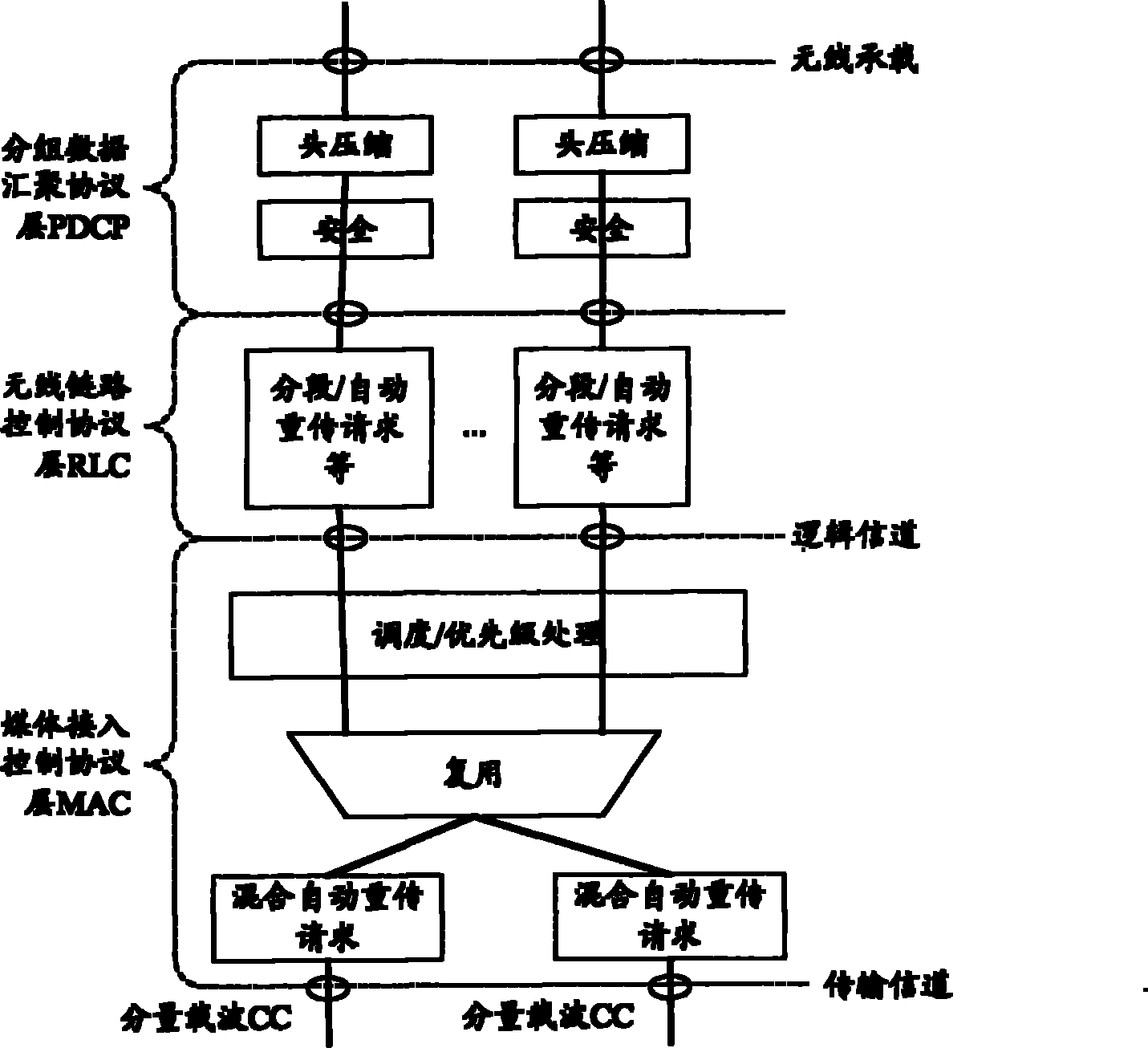
[0052] If the BSR is triggered, that is, the BSR is triggered for the first time or the BSR is triggered at least once after sending the BSR, in the case that the CC that sends the BSR (assumed to be CC1) is agreed, because there is an uplink authorization DS grant on the corresponding HARQ entity1, such as Figure 4 As shown, the UE generates a MAC CE carrying a BSR and sends it on CC1 (that is, occupies the DS grant of HARQentity1). Assuming that in this embodiment, the HARQ entity1 has no uplink grant, the UE can optionally generate a MAC CE carrying the BSR and send it on CC2 (that is, occupy the DS grant of the HARQ entity2). If there is no CC agreed to send BSR, since both CC1 and CC2 have uplink authorization, the UE generates a MAC CE carrying BSR, and can choose to send it on CC1 and / or CC2 (that is, occupies HARQ entity1 a...
Embodiment 2
[0068] In this embodiment, the UE has a DS grant from the uplink grant of HARQentity1 corresponding to CC1; and a RAR grant from the uplink grant of HARQentity2 corresponding to CC2.
[0069] If CC2 is performing a contention-based random access process, the UE generates a MAC CE carrying a C-RNTI and sends it on CC2 (that is, occupies the RAR grant of HARQ entity2); if CC2 is conducting a non-contention-based random access process In the entry process, the UE does not generate a MAC CE carrying the C-RNTI.
[0070] The processing of the BSR and the PHR is similar to that of the first embodiment, and will not be repeated here.
[0071] The processing of the data of the logical channel is similar to that in (1) and (2) of Embodiment 1. The priority of the uplink grant is in addition to the principles of the size of the uplink grant, the priority of the corresponding CC, and the channel quality described in the embodiment. In addition, because the types of the two uplink grants...
Embodiment 3
[0073] The UE has a DS grant, which comes from the uplink grant of HARQ entity1 corresponding to CC1; an SPS grant, which comes from the uplink grant of HARQ entity2 corresponding to CC2.
[0074] The processing of the BSR and the PHR is similar to that of the first embodiment, and will not be repeated here.
[0075] Since the SPS grant is a resource allocated according to the characteristics of the SPS service (such as the VoIP service, namely DRB1), in this embodiment, the data of DRB1 is preferentially selected for the uplink grant of HARQ entity2 on the basis of the existing uplink grant.
[0076] (1) Combination of remaining resources
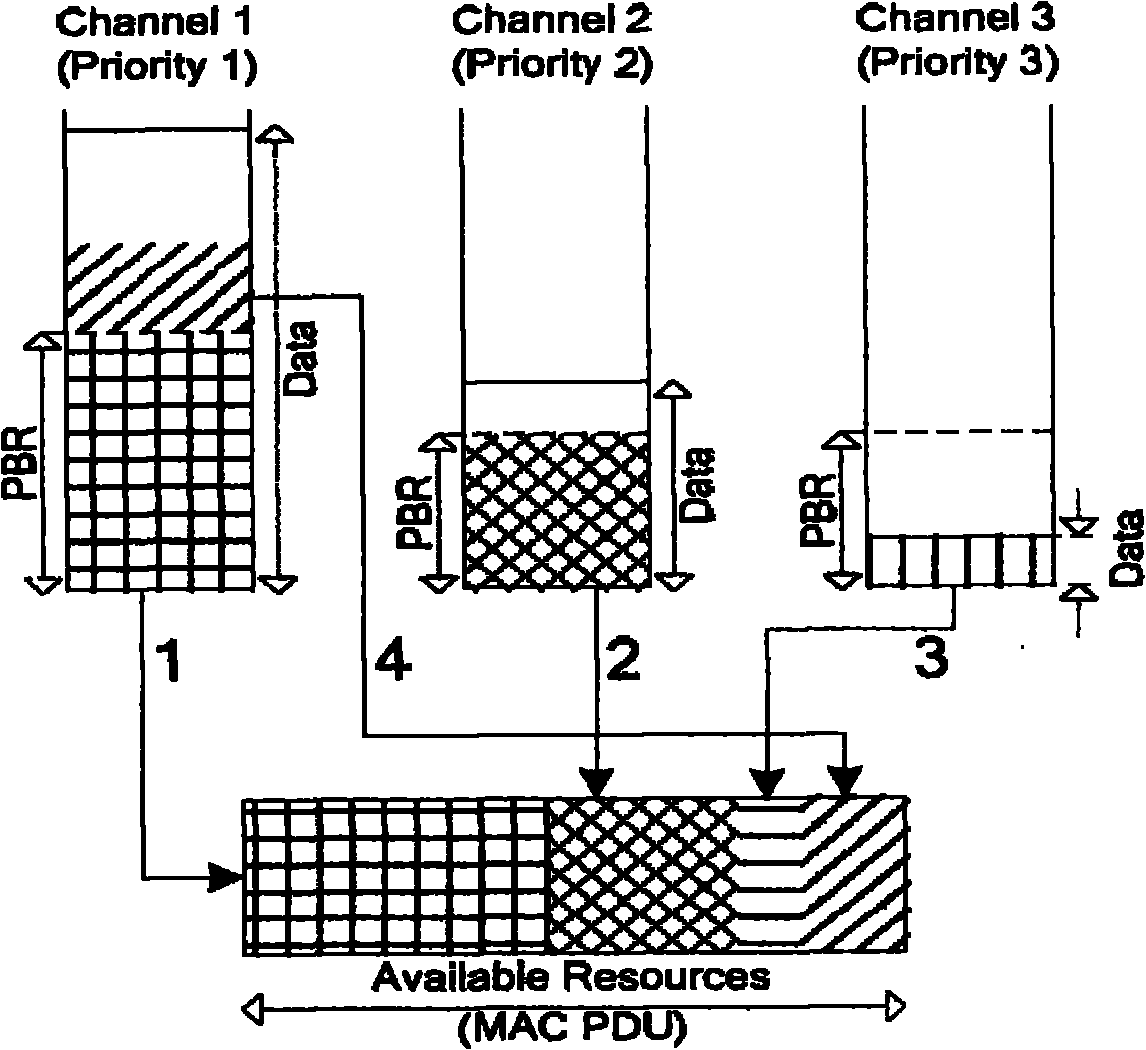
[0077] Such as Image 6 As shown, the uplink resources that can be used to send the data of the above logical channel total 1900 bits. According to the existing LCP process, it is possible to send 400 bits of data for SRB1, 400 bits for data of SRB2, 600 bits for data of DRB 1, and 600 bits for data of DRB2. 300 bits of data, and 200 bit...
PUM
 Abstract
Description
Claims
Application Information
 - R&D Engineer
- R&D Manager
- IP Professional
- Industry Leading Data Capabilities
- Powerful AI technology
- Patent DNA Extraction
Browse by: Latest US Patents, China's latest patents, Technical Efficacy Thesaurus, Application Domain, Technology Topic.
© 2024 PatSnap. All rights reserved.Legal|Privacy policy|Modern Slavery Act Transparency Statement|Sitemap


