
Device for reducing towing loss and abrasion of wet dual-clutch

A wet double clutch and clutch technology, which is applied in clutches, friction clutches, mechanically driven clutches, etc., can solve the difficulty of increasing the unevenness and uncertainty of the driven plate slip and wear, and affect the smoothness and ride comfort of the car's shifting process In order to improve the smoothness of gear shifting and ride comfort, avoid premature failure, and simplify the structure

Inactive Publication Date: 2011-08-17
ZHEJIANG WANGLIYANG TRANMISSION CO LTD
View PDF8 Cites 6 Cited by
  • Summary
  • Abstract
  • Description
  • Claims
  • Application Information

AI Technical Summary

Problems solved by technology

Due to the non-linear slipping time of clutch engagement and disengagement and the displacement of the clutch pressure plate during dual-clutch gear shifting, in a engagement-disengagement cycle, the degree of wear of each driven plate is not the same, resulting in individual driven plates being overwhelmed. Early failure, affecting the entire clutch life
In addition, in the process of clutch engagement and separation, the non-uniformity and uncertainty of the sliding wear of the driven plate increase the difficulty of control for the dual clutch that requires precise control, which directly affects the smoothness and ride comfort of the car's shifting process. comfort
[0004] The existing wet double clutch products completely rely on the friction between the driving plate and the driven plate to realize the adjustment of the gap, and there is no special structure to improve this deficiency

Method used


Image

  • Device for reducing towing loss and abrasion of wet dual-clutch
  • Device for reducing towing loss and abrasion of wet dual-clutch

Examples


Embodiment Construction

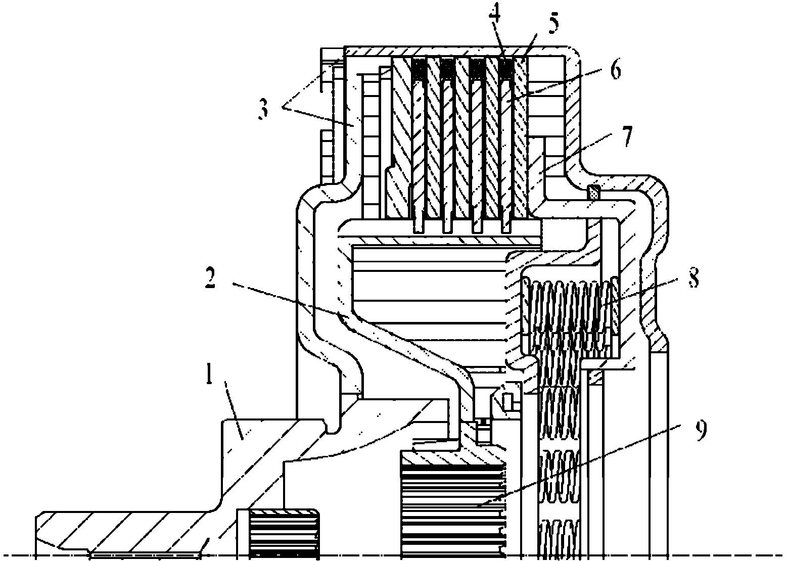
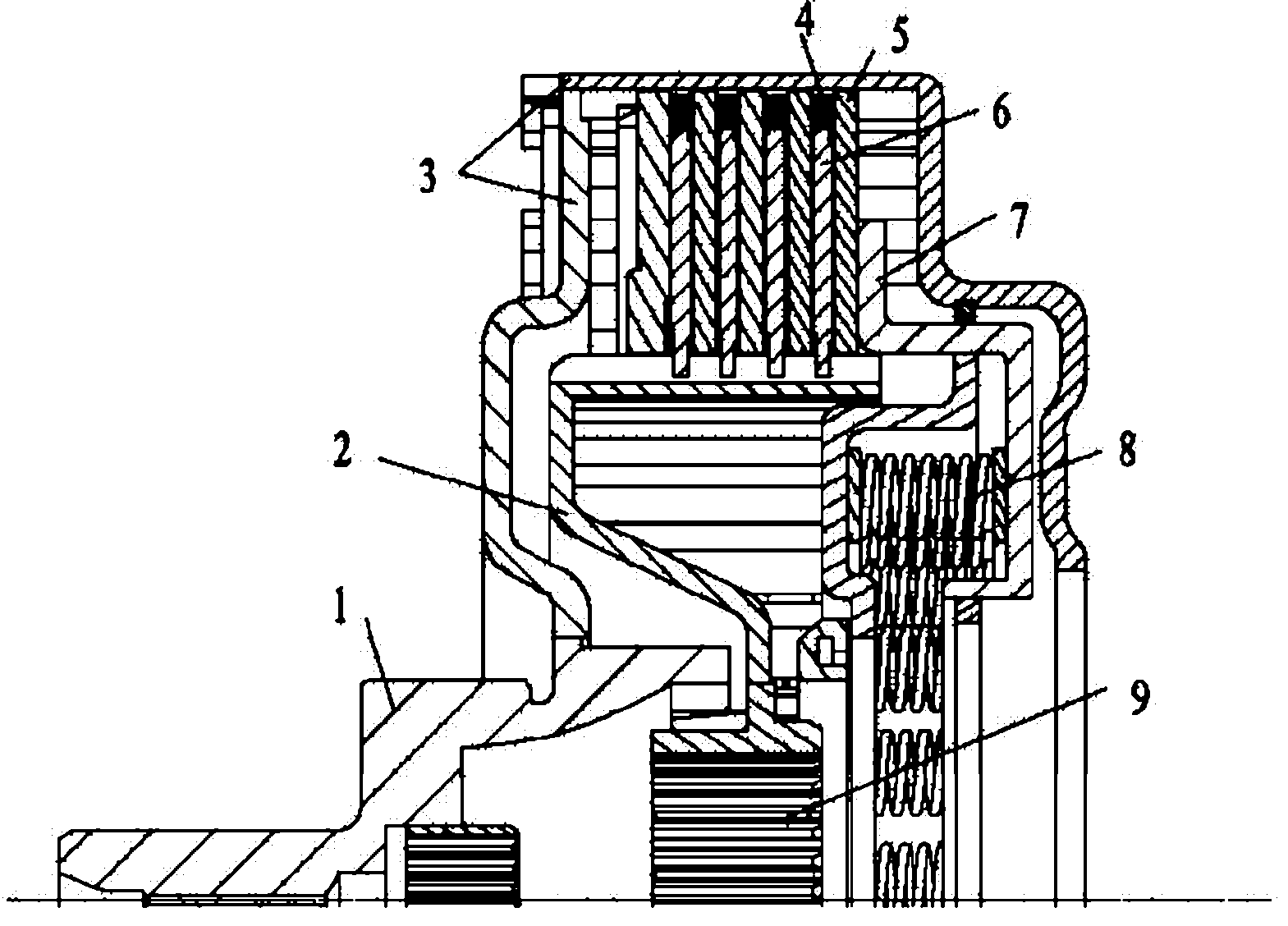
[0011] Such as figure 1 As shown, a device for reducing the loss and wear of the wet double clutch band, including the input shaft 1, the driven plate 2, the clutch housing 3, the driving plate 5, the driven plate 6, the clutch pressure plate 7, the return The spring 8 and the output shaft 9 are characterized in that: the separation spring 4 is distributed along the circumference on the protruding part where the active plate 5 cooperates with the clutch housing 3, and the separation spring 4 is fixed on the active plate 5 by bolts.

[0012] The separation spring 4 of the present invention can be selected according to the distance between the two active plates 5. It can be a helical spring or other elastic elements such as spring plates. The bolt can also be in other ways, as long as the separation spring 4 and the active plate 5 are connected Just fix it.

[0013] The separation spring 4 of the present invention should be three or more, distributed as evenly as possible along...


PUM


Abstract

The invention belongs to clutches, in particular to a device for reducing the towing loss and abrasion of wet dual-clutch. The device comprises an input shaft, a driven disk, a clutch shell, a driving plate, a driven plate, a clutch pressure plate, a return spring and an output shaft and is characterized in that release springs are distributed along the periphery of projections of the driving plate, and the projections are matched with the clutch shell, the release springs are fixed on the driving plate by bolts, there or more than three of release springs are adopted and are uniformly distributed as far as possible according to the number of the projections on the driving plate and are arranged at the same side. The device has a simple structure, is safe and reliable, is convenient to machine and manufacture and effectively solves the problem of non-uniform gaps of the driving plate and the driven plate in a combination and separation process of a wet multi-disc clutch and at the separation state of the wet multi-disc clutch on the condition that the less cost is increased, thereby reducing the towing loss of the clutch at the separation state, ensuring the clutch to effectively separate and uniformly combine during shifting, prolonging the service life, increasing the accuracy of shifting control and improving the smoothness of automobile shifting and riding comfortableness.

Description

technical field [0001] The invention belongs to the category of clutches, in particular to a device for reducing the loss and wear of a wet double clutch belt row. Background technique [0002] The wet dual clutch is generally composed of two multi-friction wet clutches. During normal driving, one clutch is usually in the engaged state and the other clutch is in the disengaged state. When the car is in the P and N gears, the two clutches are in the disengaged state at the same time. . Regardless of the working condition of the car, at least one clutch is in a disengaged state. Since the relative speed of the driving plate and the driven plate in the separated state is relatively high, if the gap between the active plates is uneven, the active plate with too small gap will be in contact with the driven plate. Friction occurs between the driven plates, resulting in additional friction torque, which reduces the transmission efficiency and increases the wear of the correspondin...

Claims


Application Information

Patent Timeline
Patent Type & Authority Applications(China)
IPC IPC(8): F16D13/52
Inventor 陈德民孙伟任华林麻越垠郭晓林王涛刘国强夏伟强陆晓平史小飞
Owner ZHEJIANG WANGLIYANG TRANMISSION CO LTD
Learn More