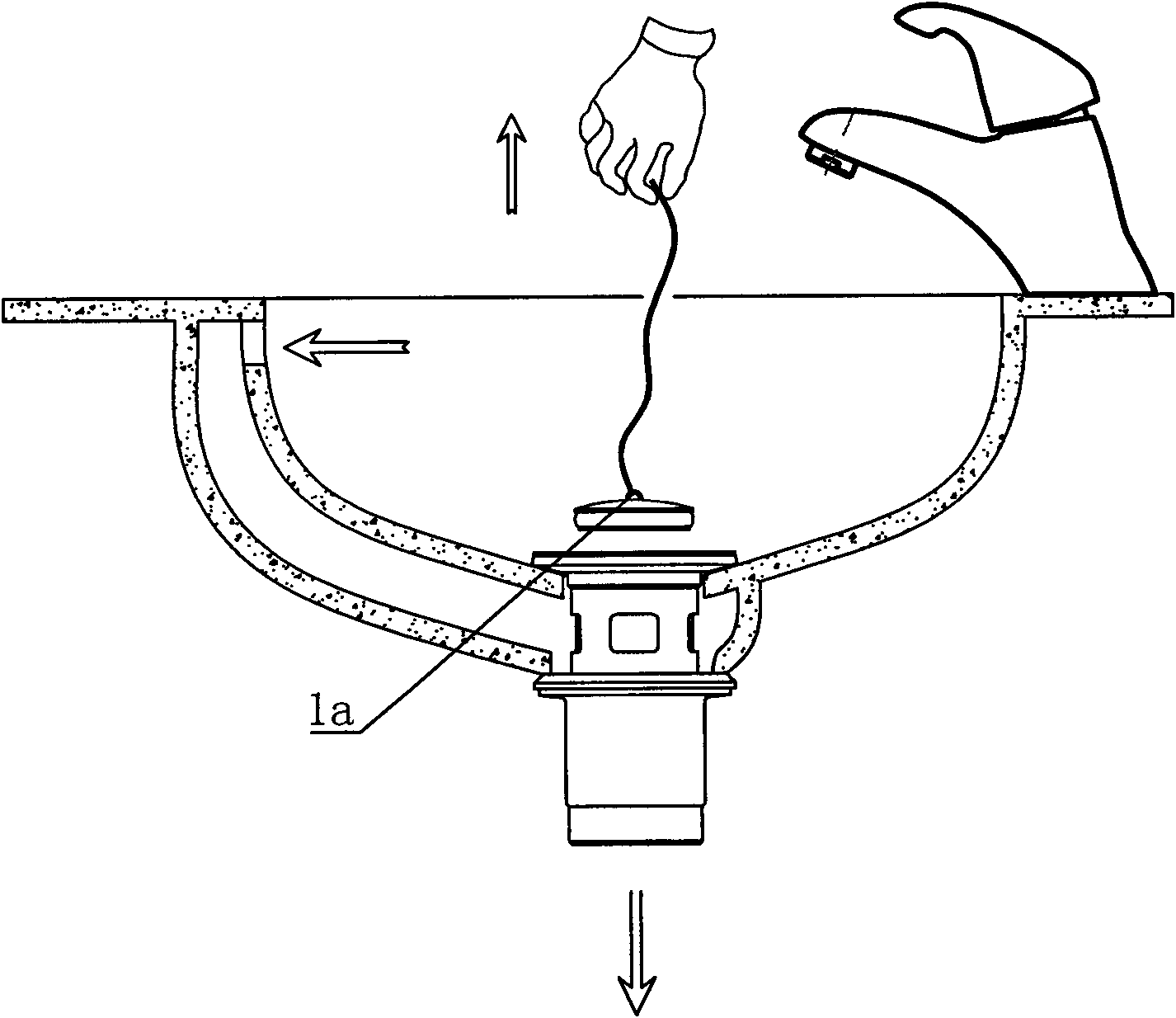
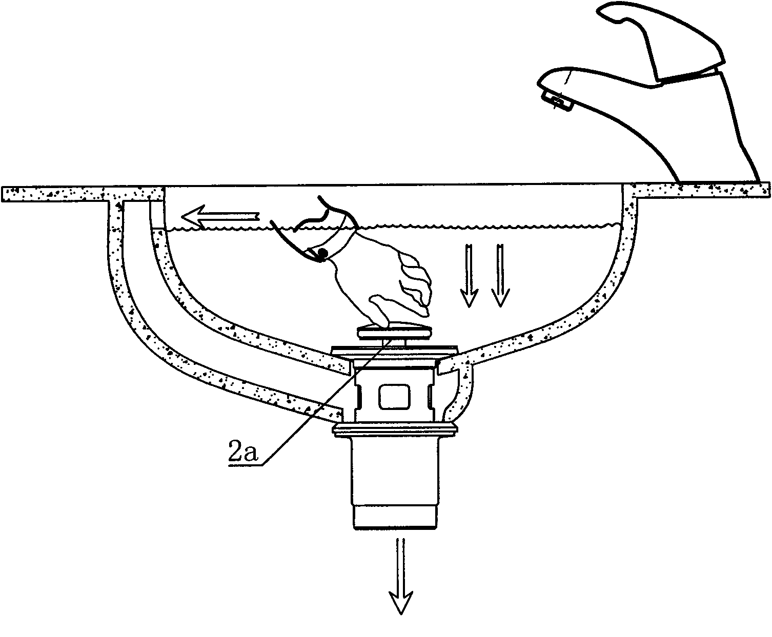
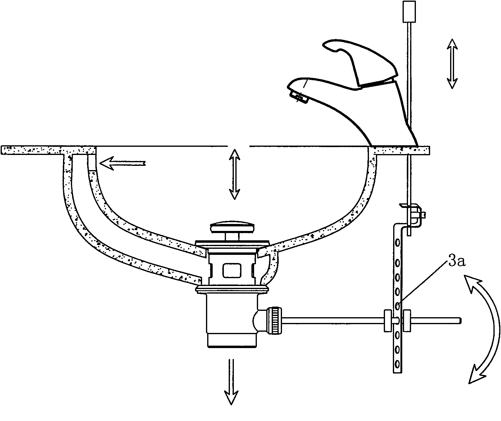
Tap of controlling turning on and turning off of drainer of adapted basin by hydraulic pressure and current output and matched structure thereof
A basin drainer and output control technology, which is applied in the field of basin drainers equipped with faucets and faucets, can solve the problems of easy breakage of chains, limited space for installation and combination, and easy loss, etc., to reduce hole positions, fast and convenient installation and maintenance, Easy to clean effect
- Summary
- Abstract
- Description
- Claims
- Application Information
AI Technical Summary
Problems solved by technology
Method used
Image
Examples
Embodiment 1
[0046] Such as Figure 6-Figure 14As shown, the present invention has a water pressure water flow output control and is equipped with a basin drainer to open and close the faucet. The water control device 3 for opening and closing, the water supply channel chamber of the faucet main body 1 is provided with a diversion water outlet guide hole, and the diversion water outlet guide hole is connected to the water control device 3 through a pipeline. Wherein, there are one or more diversion outlet water guide holes, and there are also one or more corresponding pipelines. A control switch 4 for controlling the water pressure is arranged between the water diversion guide hole and the water control device 3 of the water remover 2. The control switch is arranged on the main body of the faucet, or is set at the upper and lower, front and rear positions. The control switch is a combined type or Single control. In this embodiment, the control switch 4 adopts a push-type switch, includin...
Embodiment 2
[0050] Such as Figure 15 - Figure 1 As shown in 9, the difference between this embodiment and the above-mentioned embodiment is that the control switch 4 adopts a knob type or a lever type switch, including a valve body 4-21 and a sealing ring 4-22 arranged in sequence inside it, a sealing Fixed tile 4-23, sealed movable tile 4-24, sealed movable tile 4-24 is connected with a valve shaft 4-25, the valve shaft 4-25 passes through the valve body 4-21, and sealed fixed tile 4-25 23 and the sealing movable tile 4-24 are respectively provided with two water inlet holes 4-26 that cooperate with each other.
[0051] During use, the knob or lever of the control switch is rotated to drive the movable sealing tile to rotate, the fixed sealing tile and the two water inlet holes on the movable sealing tile are connected one by one, and the water flow output from the diversion outlet water guide hole Enter the water control device through the control switch; then rotate a certain angle, ...
Embodiment 3
[0053] Such as Figure 20 - Figure 2 As shown in 3, the difference between this embodiment and the above two embodiments is that the pipes that are diverted by the hydraulic water flow are double pipes, that is, the form of double control pipes is adopted, and two inlets are arranged on the single water control device 3. The water interface 5, the water inlet interface 5 of a single water control device 3 is connected to the water outlet guide hole through two control output pipes 6 . Wherein, the water control device 3 includes a hydraulic cylinder 3-21 and a push rod 3-22 provided therein, a return spring 3-23, the return spring 3-23 is set outside the push rod 3-22, and the push rod 3-22 tops Pressed on the water seal cover 7 of the water remover, one of the water inlet ports 5 is connected to the hydraulic cylinder 3-21 of the water control device 3, and the other water inlet port 5 is connected to the water drain outside the hydraulic cylinder 3-21. The inner cavity of t...
PUM
 Abstract
Description
Claims
Application Information
 - R&D
- Intellectual Property
- Life Sciences
- Materials
- Tech Scout
- Unparalleled Data Quality
- Higher Quality Content
- 60% Fewer Hallucinations
Browse by: Latest US Patents, China's latest patents, Technical Efficacy Thesaurus, Application Domain, Technology Topic, Popular Technical Reports.
© 2025 PatSnap. All rights reserved.Legal|Privacy policy|Modern Slavery Act Transparency Statement|Sitemap|About US| Contact US: help@patsnap.com


