Charge-discharge test equipment for medium material

A charge-discharge test, dielectric material technology, applied in the field of testing, can solve the problems of different research purposes, different numbers of electrodes, regardless of storage time and quantity, etc.

Active Publication Date: 2011-08-24
NO 510 INST THE FIFTH RES INST OFCHINA AEROSPAE SCI & TECH
View PDF5 Cites 19 Cited by
  • Summary
  • Abstract
  • Description
  • Claims
  • Application Information

AI Technical Summary

Problems solved by technology

[0004] The conventional conductivity measurement method is not completely suitable for the space charged environment. The main reasons why the conventional method is not suitable for the space condition are as follows: (1) The charge injection method is different, and the charged charge density curve and electric field formed are also essentially different: conventional The voltage of the three-electrode method is provided by a power supply, and the charged surface potential of the medium is formed by charge injection; (2) the number of electrodes is different: the conventional three-electrode method has electrodes on both sides of the medi

Method used


Image

  • Charge-discharge test equipment for medium material
  • Charge-discharge test equipment for medium material
  • Charge-discharge test equipment for medium material

Examples


Embodiment Construction

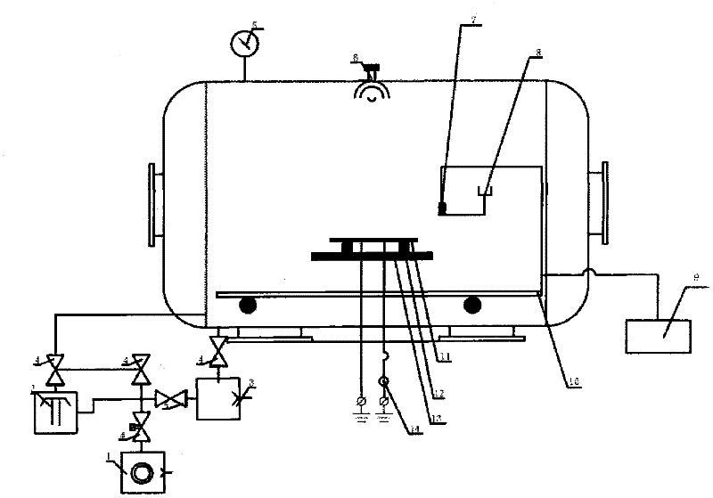
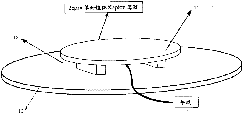
[0025] The testing equipment in the present invention includes a vacuum system, a charging and discharging system, and a potential testing system. The vacuum system includes a vacuum tank, a mechanical pump 3, a diffusion pump 2, a multistage rotary vane pump 1, valves, sealed pipelines and a workbench; the charging and discharging system consists of an electron gun 6 and a sample 11 installation system; the potential testing system includes a potentiometer 9 and microcurrent meter 14, vacuum valve 4 and vacuum gauge 5 are placed in the vacuum tank.

[0026] The connection relationship of this system is: the vacuum tank is placed on the workbench, connected to the mechanical pump through one sealed pipeline through the baffle valve A15, connected to the diffusion pump 2 through the other sealed pipeline through the baffle valve B16, and mechanical pump 3 , multi-stage rotary vane pump 1, and diffusion pump 2 form the pumping unit in the vacuum system; the electron gun 6 is loc...


PUM


Abstract

The invention discloses charge-discharge test equipment for a medium material. The charge-discharge test equipment comprises a vacuum system, a charge-discharge system and a potential test system, wherein the vacuum system comprises a vacuum tank, a mechanical pump (3), a diffusion pump (2), a multistage rotary vane pump (1), a valve, a sealing pipeline and a workbench; the charge-discharge system comprises an electronic gun (6) and a sample (11) mounting system; the potential test system comprises a potentiometer (9) and a micro current meter (14); a vacuum valve (4) and a vacuum gauge (5) are arranged in the vacuum tank; in addition, a baffle valve A (15), a baffle valve B (16) and a copper plate (13) are further provided; in conclusion, the equipment measures the attenuation relation of surface potential with time by using a surface potential probe, and the conductivity of the sample can be calculated according to the measured sample surface attenuation potentials at different moments. The conductivity test equipment provided by the invention is suitable for estimating deep charging hazard, and can supply valuable engineering data to protection of deep charging and discharging effect.

Description

technical field [0001] The invention relates to a dielectric material charging and discharging testing device, in particular to a dielectric material surface potential testing system in a vacuum environment, which belongs to the testing field. Background technique [0002] In order to reduce the launch weight and meet the electrical, thermal and mechanical performance requirements of the spacecraft, a large amount of organic dielectric materials are used in the spacecraft. In the space radiation environment, high-energy particles and plasma are easy to deposit inside the dielectric material on the periphery of the spacecraft or on the dielectric material inside the spacecraft through the shielding layer. When the potential difference between the surface of these dielectric materials and other surrounding components or the electric field generated by the deposited charge exceeds a certain threshold, high-energy discharge will directly cause the breakdown of sensitive electron...

Claims


Application Information

Patent Timeline
IPC IPC(8): G01R27/02
Inventor 李存惠柳青史亮秦晓刚马亚莉
Owner NO 510 INST THE FIFTH RES INST OFCHINA AEROSPAE SCI & TECH
Why Eureka
Try Eureka