Distributed lighting control system

A technology of illuminators and controllers, which is applied in the direction of lighting devices, lighting auxiliary devices, lighting and heating equipment, etc., and can solve problems such as difficult reconfiguration, difficult installation, and high cost

Inactive Publication Date: 2011-09-07
IDC LLC
View PDF4 Cites 16 Cited by
  • Summary
  • Abstract
  • Description
  • Claims
  • Application Information

AI Technical Summary

Problems solved by technology

[0012] In all current practices, installation is difficult, expensive and time consuming
In all current practices, reconfiguration is difficult, expensive and time consuming
In all current conventions, control modes are limited and constrained in how they apply to global fixture collections, fixture groups, and individual fixtures

Method used


Image

  • Distributed lighting control system
  • Distributed lighting control system
  • Distributed lighting control system

Examples


Embodiment Construction

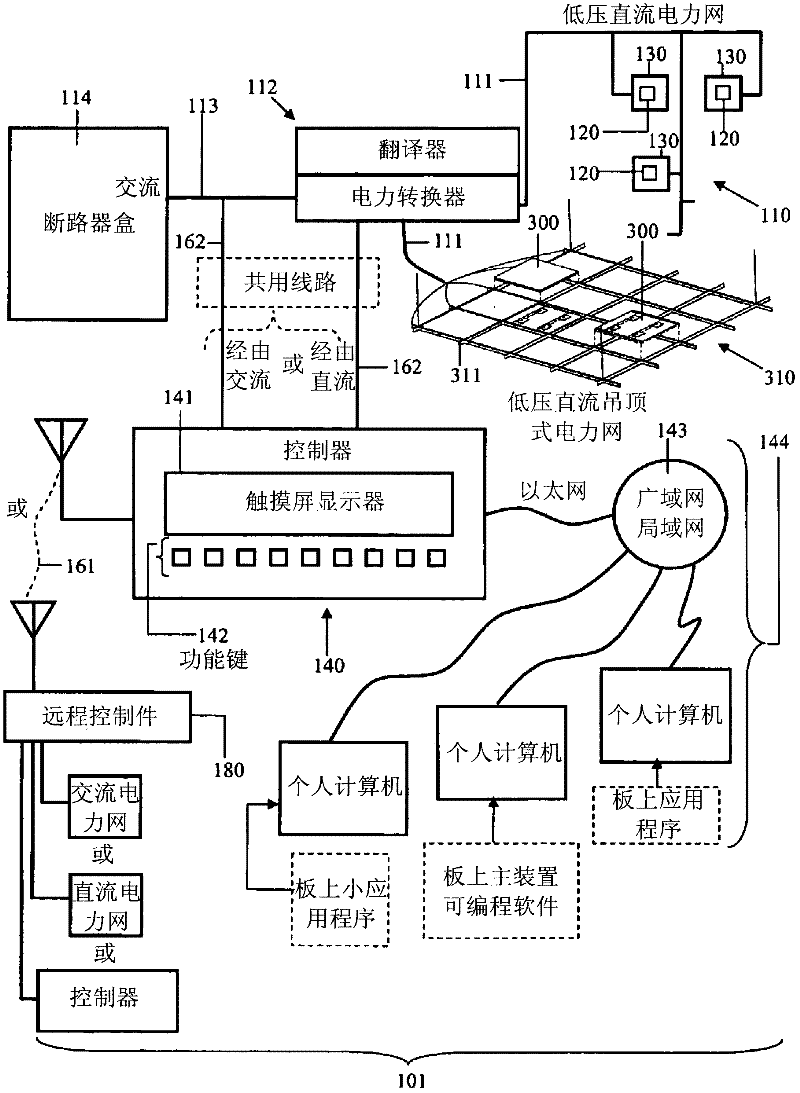
[0022] The present invention is directed to systems and methods for providing distributed lighting control. The Distributed Lighting Control System (DLCS) 101 enables numerous luminaires 120 of different types and capabilities to be installed in different types of installations without the installer paying attention to what types of wires have been pulled or (other than to open the circuit) Apart from the primary concern of overloading the circuit breaker and circuit) the details of where the wires have been pulled are ignored. The intelligence embedded in the controller and in the luminaire 120 itself enables an unprecedented level of system control and enables that control to be instantiated post-installation. This dramatic shift in lighting configuration and installation significantly reduces cost and complexity while increasing performance and flexibility.

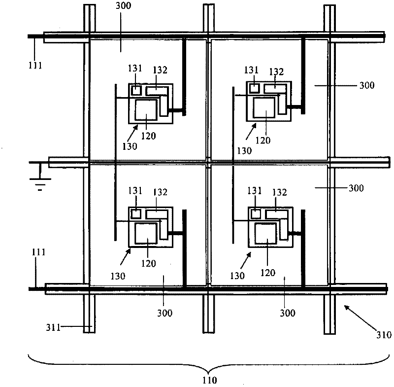
[0023] Figure 1A One embodiment of DLCS 101 is illustrated. In general, the DLCS 101 includes: a power grid 110;...


PUM


Abstract

The Distributed Lighting Control System (DLCS) is based upon a distributed lighting system, which imbeds luminaire devices in structural materials such as ceiling tiles and wallboard. Each luminaire device is attached to a power network, and each luminaire device includes, or is directly associated with, an electronic circuit component that controls the activation and operation of the luminaire. In normal operation the power network is energized and the electronic circuit controls when and how the luminaire itself is energized based on signals conveyed to the circuit through wireless means or through signals imposed upon the power grid. Said signals are generated by the DLCS-controller, which is resident within the structure that contains the DLCS.

Description

[0001] Related Application Cross Reference [0002] This application is generally related to a co-pending application entitled "Distributed Illumination System" filed concurrently therewith. This application claims priority over provisional application U.S. Application 61 / 104,460, filed October 10, 2008, entitled "Distributed Lighting Control System," which is published in its entirety at Incorporated herein by reference. Background technique [0003] This section is intended to provide a background or context to the invention that is particularly set forth in the claims. The description herein may include concepts that could be practiced, but are not necessarily concepts that have been previously conceived or pursued. Therefore, unless otherwise indicated herein, what is described in this section is not prior art to the description and claims in this application and is not admitted to be prior art by inclusion of this section. [0004] Consumers demand more complex lighti...

Claims


Application Information

Patent Timeline
Patent Type & Authority Applications(China)
IPC IPC(8): H05B37/02
CPCH05B37/0245H05B47/175F21V21/02H05B45/37
Inventor 杰弗里·B·桑普塞尔
Owner IDC LLC
Why Eureka
Try Eureka