Button mount for a lighting control

a technology of lighting control and button mounting system, which is applied in the direction of contact mechanisms, instruments, electrical apparatus, etc., can solve the problems of fatigue failure at the junction of the legs and less than ideal operating conditions for the flexing button

Active Publication Date: 2011-03-22
LUTRON TECH CO LLC
View PDF11 Cites 13 Cited by
  • Summary
  • Abstract
  • Description
  • Claims
  • Application Information

AI Technical Summary

Problems solved by technology

The integral construction of the button supports 12 from the same material as the button 10, although facilitating fabrication, results in less than ideal operating conditions for the flexing button supports 12.
Such heating of the polycarbonate and repeated flexing of the legs 16 can lead to fatigue failures at the junctions between the legs 16 and the tabs 14.

Method used


Image

  • Button mount for a lighting control
  • Button mount for a lighting control
  • Button mount for a lighting control

Examples


Embodiment Construction

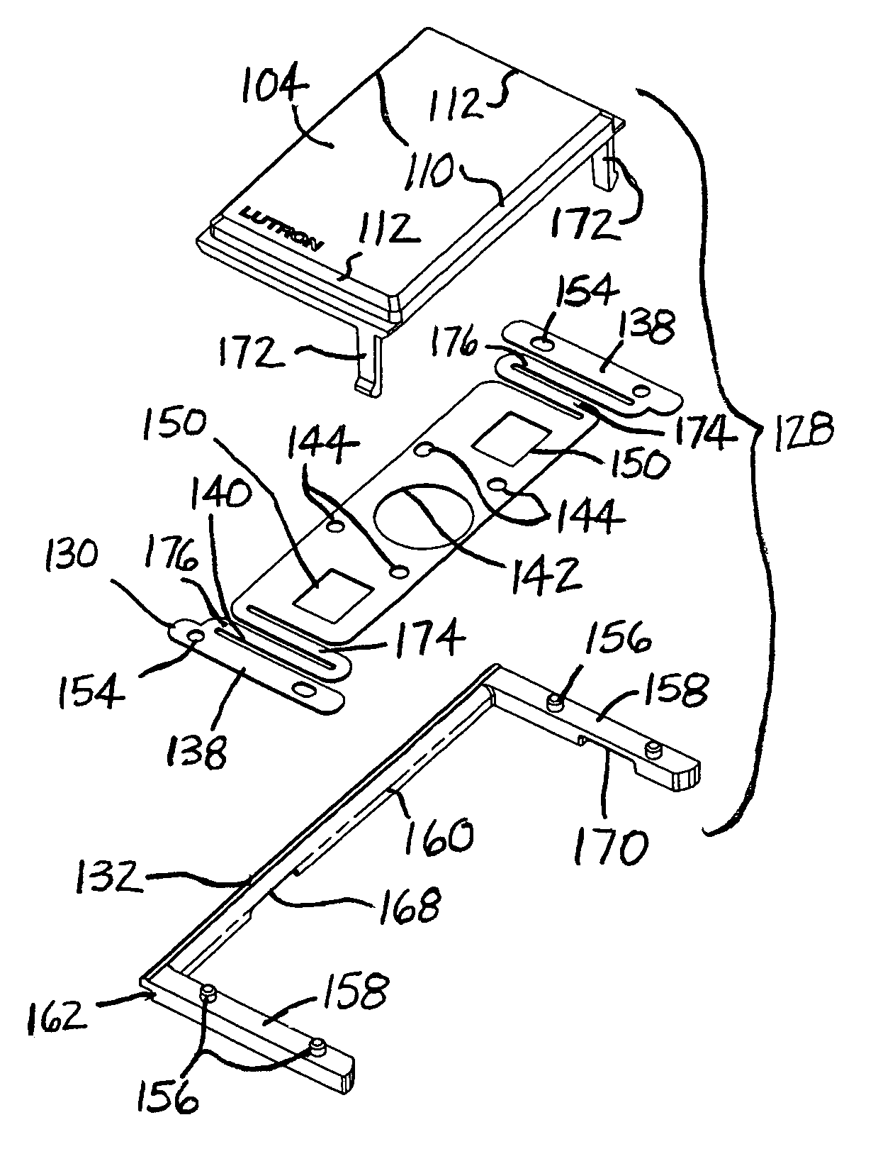
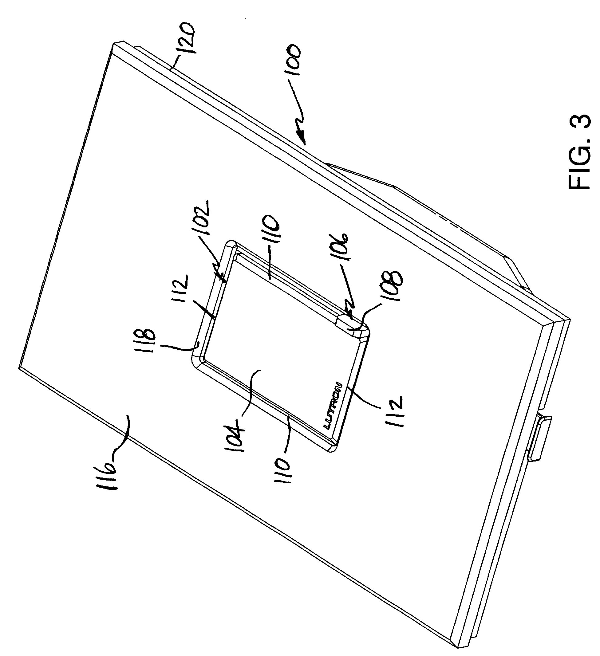
[0022]Referring to the drawings, where like numerals identify like elements, there is shown in FIGS. 3 and 4 a lighting control 100 according to an exemplary embodiment of the invention. The lighting control 100 includes an on / off mechanism 102 having a button 104 and a dimmer mechanism 106 having a slide actuator 108 located next to the button 104. The button 104 is generally rectangular including opposite sides 110 defining a length (along the Y-axis) and opposite ends 112 defining a width (along the X-axis). As described below in greater detail, the lighting control 100 includes a button mounting system that provides multiple degrees of freedom of movement for the button 104. This arrangement provides for varying motions of the button 104 depending on the portion of the button 104 contacted by a user to actuate the on / off mechanism 102. The differing motions of the button 104, however, are transferred to an underlying hinge bar 114 (FIG. 9) to provide for a uniform actuating moti...


PUM


Abstract

A mounting system for a button includes first and second spring elements located adjacent opposite ends of the button. Each of the spring elements includes a serpentine portion capable of multiple degrees of freedom of movement providing varying actuating motions for the button. The spring elements may be defined by a plate also having a center portion secured to the button and opposite end portions secured to a base. According to one embodiment, the button is made from a thermoplastic material and the plate is metal.

Description

FIELD OF THE INVENTION[0001]The present invention relates to lighting controls and more particularly to a button mounting system for a lighting control.BACKGROUND OF THE INVENTION[0002]Known lighting controls include an on / off mechanism having a button that actuates a momentary tactile switch when the button is pressed by a user. The on / off button of the Vareo® lighting control by Lutron Electronics Co., Inc. of Coopersburg, Pa. is located next to a slide actuator of a dimmer mechanism. Referring to FIGS. 1 and 2, the prior on / off button 10 of the Vareo® lighting control is shown separately from the lighting control along with flexible button supports 12 located at opposite ends of the button 10. The button supports 12 are integrally molded with the button 10 from a thermoplastic material such as polycarbonate.[0003]Each of the button supports 12 includes a tab 14 connected to one of the ends of button 10 and a pair of elongated legs 16 extending from opposite sides of the tab 14. A...

Claims


Application Information

Patent Timeline
Patent Type & Authority Patents(United States)
IPC IPC(8): H01H13/70
CPCH01H3/122H01H13/14H01H13/52
Inventor HIBSHMAN, THOMAS E.MACK, ADAM M.
Owner LUTRON TECH CO LLC
Why Eureka
Try Eureka