Lighting system

a technology of lighting system and conversion module, which is applied in the field of lighting system, can solve the problems of inability to carry out, inability to compensate the outage of a conversion module by the redundancy device of the known lighting system, and the availability and security of the conversion module used in the lighting system, so as to improve the availability and reliability of the lighting system. the effect of security

Active Publication Date: 2017-03-07
MA LIGHTING TECH
View PDF5 Cites 15 Cited by
  • Summary
  • Abstract
  • Description
  • Claims
  • Application Information

AI Technical Summary

Benefits of technology

[0008]Therefore, the object of the present invention is to provide a lighting system with which the security, the availability and the reliability of the lighting system can be further improved. In addition, it is the object of the present invention to provide a conversion module and a switch-over module for setting up the lighting system according to the invention.

Problems solved by technology

The control programs for controlling the lighting system can be highly complex data processing programs with which several thousand lighting devices have to be actuated at the same time.
This redundancy is in particular of vital importance with large live stage shows since an outage of the data network would otherwise make it impossible to carry out the event at all.
When using the generic lighting systems, one problem is the reliability, the availability and the security of the conversion modules used in the lighting system.
Since the conversion modules ultimately are the terminal station for the redundantly designed data networks, an outage of a conversion module cannot be compensated by the redundancy devices of the known lighting systems.
With the known lighting systems, an outage of a conversion module rather means that all lighting devices connected to the conversion module cannot be actuated anymore and thus fail.

Method used


Image

  • Lighting system
  • Lighting system

Examples


Embodiment Construction

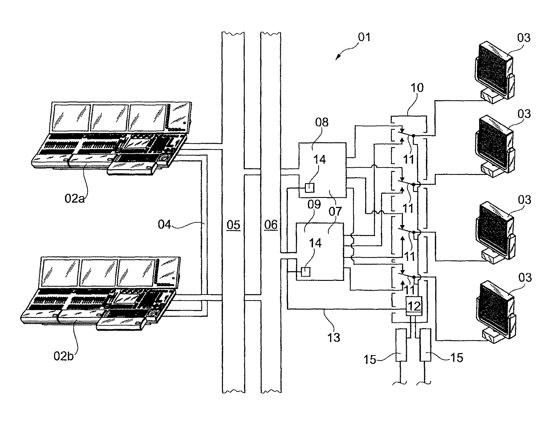
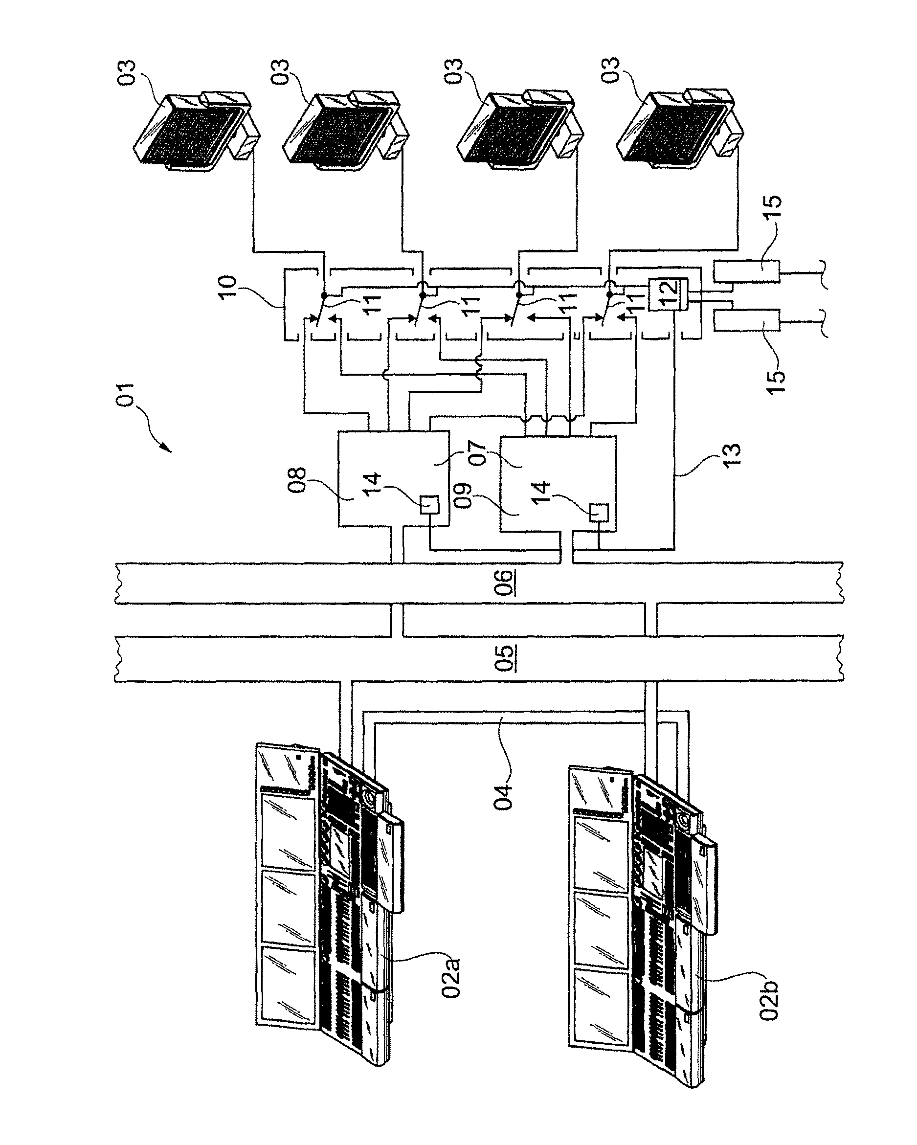
[0024]In FIG. 1, a lighting system 01 comprising two lighting control consoles 02 for actuating a plurality of lighting devices 03 is schematically illustrated. Here, the two lighting control consoles 02 operate redundantly and are connected to each other via a data line 04, in order to synchronize the data processing in the two lighting control consoles 02.

[0025]The control data generated in the lighting control console 02a are transmitted via a first digital data network05, for instance an internet data network. The digital control data generated in the lighting control console 02b, however, are transmitted via a second digital data network 06. The two data networks 05 and 06 thus form a redundant data structure, such that, in case of an outage of one of the two data networks, its activity can be taken over by the other data network. The digital control data generated by the lighting control consoles 02 and transmitted in the data networks 05 and 06 cannot be processed directly in...


PUM


Abstract

A lighting system includes at least one lighting control console for controlling lighting devices, at least two redundant data networks, at least one conversion module, and at least one lighting device actuated by the DMX control data of the conversion module. The conversion module includes at least two redundant conversion devices. At least one switch-over device is interconnected between the two conversion devices on the one side and at least one lighting device actuated by the conversion devices on the other side. The two conversion devices on the one side and the switch-over device on the other side are connected to one another via at least one monitoring data line over which monitoring signals are transmitted. The switch-over device can be switched depending on the monitoring signals.

Description

CROSS REFERENCE TO RELATED APPLICATION[0001]Not Applicable.STATEMENT REGARDING FEDERALLY SPONSORED RESEARCH OR DEVELOPMENT[0002]Not applicable.FIELD OF THE INVENTION[0003]The invention relates to a lighting system as used in particular for illuminating stages and concert halls.BACKGROUND OF THE INVENTION[0004]In particular, but by no means exclusively, generic lighting systems are used for professionally lighting stages and concert halls. Here, the lighting system is controlled by at least one lighting control console, in which the control data for actuating the multiple lighting devices, which can be spotlights, LED panels or other types of stage lighting devices, are generated, managed, stored and output to the lighting devices. To this effect, the lighting control console is based on digital data technology and thus comprises a digital processor and at least one digital memory. The control programs for controlling the lighting system can be highly complex data processing programs...

Claims


Application Information

Patent Timeline
Patent Type & Authority Patents(United States)
IPC IPC(8): H05B37/02H05B33/08H05B44/00
CPCH05B37/0245H05B33/086H05B37/02H05B37/029H05B37/0254H05B47/175H05B47/10H05B47/18H05B47/155
Inventor ADENAU, MICHAEL
Owner MA LIGHTING TECH
Why Eureka
Try Eureka