Fatigue characteristic evaluation method for t joint part of t-type welding joint structure

A technology of fatigue characteristics and welded joints, applied in the field of fatigue characteristics of T-joints

Inactive Publication Date: 2011-09-21
KOBE STEEL LTD
View PDF5 Cites 8 Cited by
  • Summary
  • Abstract
  • Description
  • Claims
  • Application Information

AI Technical Summary

Problems solved by technology

However, since the method of the above-mentioned Patent Document 1 does not study the material properties of the welded jo

Method used


Image

  • Fatigue characteristic evaluation method for t joint part of t-type welding joint structure
  • Fatigue characteristic evaluation method for t joint part of t-type welding joint structure
  • Fatigue characteristic evaluation method for t joint part of t-type welding joint structure

Examples


Embodiment 1

[0063] In this example, a micro-notch test piece was produced as a test piece simulating a welded joint, and the fatigue characteristics and the local weld toe represented by the above formula (1) and the above formula (2) were compared when the fatigue test was performed using the above test piece. The relationship between plastic strain evaluation parameters (1) or (2) is studied.

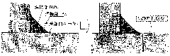
[0064] In detail, prepare Figure 5 The shown smooth plate-shaped notched test piece (a test piece having a discontinuous shape such as a welded portion, 65 mm in length x 16 mm in width x 4 mm in thickness). When this test piece is used, the stress concentration at the notch part produces local plastic strain, so the strain state of the weld toe part of the T-joint can be reproduced.

[0065] Figure 5 The fatigue characteristics (fatigue crack life) of the smooth test piece shown are obtained by dividing the load stress range Δσ (the repeated maximum stress S 1 and repeated minimum stress S ...


PUM


Abstract

The present invention provides a method which can simply and quickly evaluate a fatigue characteristic of a T joint part of a T-type welding joint structure without actual manufacturing of a welding joint for fatigue test, wherein, when a curvature radius of a weld toe of the T joint part is set to rho (mm), a uniform strain rate (%) of a welding heat effect part of the T joint part is set to UEHAZ, and a yield stress (MPa) of the welding heat effect part of the T joint part is set to YPHAZ, the fatigue characteristic of the T type welding joint structure is evaluated through using a weld toestress evaluation parameter which is represented by a formula (1): weld toe stress evaluation parameter (1)= (1.13*10-2*rho-0.59)*(1.05*10<-4>*UEHAZ+1.64*10<-2>)*(5.15*YPHAZ-0.92).

Description

technical field [0001] The present invention relates to a method for easily and quickly evaluating (predicting, estimating) the fatigue characteristics of a T-joint portion of a T-shaped welded joint structure without actually fabricating a welded joint and performing a fatigue test. The evaluation method of the present invention can be applied to various fields where T-shaped welded joint structures such as shipbuilding, marine structures, low-temperature boxes, pipelines, and civil engineering structures are applicable. Background technique [0002] Most of the failures of welded structures using thick steel plates, such as ships and machinery, are caused by fatigue cracks, and almost all of these fatigue cracks occur at welded joints. This is because the fatigue strength of the welded joint portion is significantly lower than that of the base metal. [0003] It is well known that the fatigue characteristics of the welded joint are greatly influenced by the shape (especia...

Claims


Application Information

Patent Timeline
IPC IPC(8): G01N3/32
Inventor 田村荣一高冈宏行
Owner KOBE STEEL LTD
Why Eureka
Try Eureka