Uplink transmission and uplink resource distribution method and apparatus

A transmission method and technology of a resource allocation unit, which are applied in the fields of uplink transmission and uplink resource allocation, can solve the problems of reduction of maximum transmission power, reduction of PA transmission power, and increase, and the effect of reducing transmission power reduction is achieved.

Active Publication Date: 2014-11-05
HUAWEI TEHCHNOLOGIES CO LTD
View PDF6 Cites 0 Cited by
  • Summary
  • Abstract
  • Description
  • Claims
  • Application Information

AI Technical Summary

Problems solved by technology

[0004] However, in LTE-A (LTE-Advance, the evolution of LTE), in order to make better use of frequency resources, it is proposed to transmit multiple signals that are discontinuous in frequency between each other in one uplink carrier. This discontinuous transmission causes Compared with the original LTE system, the peak-to-average ratio of the signal has increased by 4-6dB. In order to avoid nonlinear distortion, it is necessary to reduce the transmit power of the PA, resulting in a decrease in the maximum transmit power of the LTE-A UE (User Equipment, user equipment).

Method used


Image

  • Uplink transmission and uplink resource distribution method and apparatus
  • Uplink transmission and uplink resource distribution method and apparatus
  • Uplink transmission and uplink resource distribution method and apparatus

Examples


Embodiment Construction

[0040] The following will clearly and completely describe the technical solutions in the embodiments of the present invention with reference to the accompanying drawings in the embodiments of the present invention. Obviously, the described embodiments are only some, not all, embodiments of the present invention. Based on the embodiments of the present invention, all other embodiments obtained by persons of ordinary skill in the art without making creative efforts belong to the protection scope of the present invention.

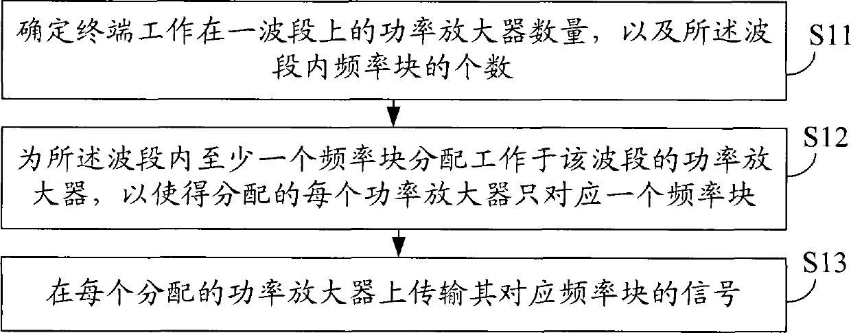
[0041] figure 1 A schematic diagram of an uplink transmission method provided by an embodiment of the present invention, the method includes:

[0042] S11: Determine the number of power amplifiers that the terminal operates on a band, and the number of frequency blocks in the band.

[0043] Terminals (which can be various types of UEs) or base stations (which can be BSs, NodeBs, eNodeBs, relay stations, and other sites that provide access services for termina...


PUM


Abstract

The embodiment of the invention discloses an uplink transmission and uplink resource distribution method and an apparatus and is directed to the field of communication technology. The method comprises the steps of determining the amount of power amplifiers whose terminals work on a wave band and the number of the frequency blocks in the wave band, distributing a power amplifier working in the wave band for at least one frequency block in the wave band to make each power amplifier distributed only correspond to one frequency block and transmitting the signal of the corresponding frequency block on each distributed power amplifier. According to the technical means, transmitting the signal on a plurality of mutually non-continuous frequency blocks in the same wave bank can be realized and the problem of reduced maximal emission power caused by a plurality of frequency blocks using a same power amplifier is relieved.

Description

technical field [0001] The present invention relates to the technical field of communications, and in particular to a method and device for uplink transmission and uplink resource allocation. Background technique [0002] In a communication system, in order to improve communication quality, the processed signal must be amplified by a PA (Power Amplifier, power amplifier) ​​to a suitable power before being transmitted. Each power amplifier has a certain operating range, and if the signal input to the power amplifier exceeds this operating range, it may cause distortion. In an actual system, the signal entering the power amplifier is generally not a non-constant envelope signal, but a dynamically changing signal within a certain dynamic range. The signal input to the power amplifier is usually amplified with the same gain, and the peak-to-average ratio of the input signal should not be too large, otherwise part of the signal will fall into the non-linear working area of ​​the...

Claims


Application Information

Patent Timeline
Patent Type & Authority Patents(China)
IPC IPC(8): H04W16/12H04W52/14H04W72/04
CPCY02B60/50
Inventor 冯淑兰张兴炜
Owner HUAWEI TEHCHNOLOGIES CO LTD
Why Eureka
Try Eureka